
Insights & Updates
pet bottle production machine
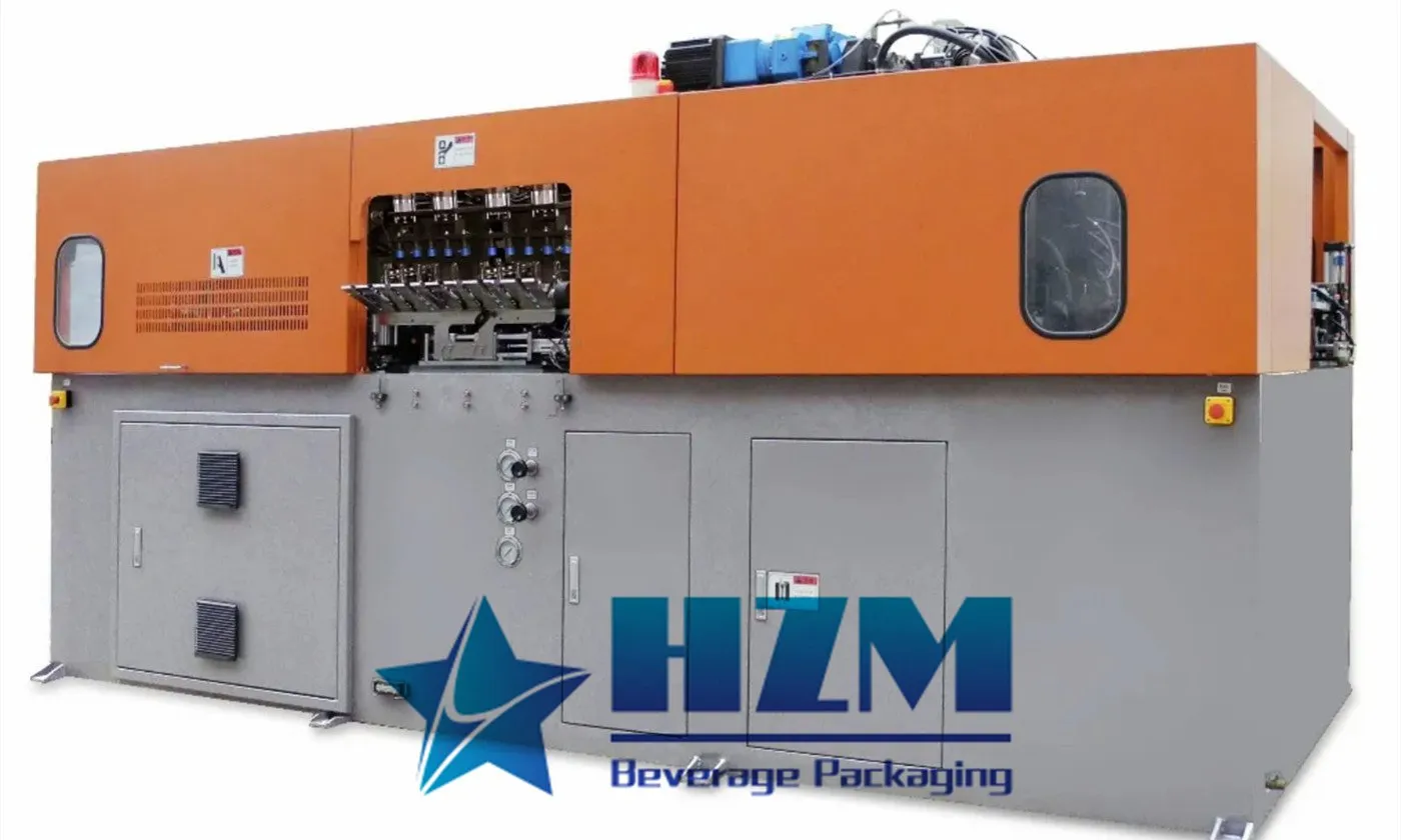
A PET bottle production machine usually means a stretch blow moulding machine that turns purchased PET preforms into bottles. Producing the preforms themselves requires a different manufacturing process and equipment. Clarifying this distinction at the start prevents a bottle-making project from being quoted as though it includes the entire route from resin to finished package.
For a water or beverage factory buying preforms, the core decisions are bottle design, preform compatibility, production rate and the utilities needed for heating, blowing and cooling. The machine should be selected around the package the factory needs, rather than choosing a cavity count first and trying to fit the bottle afterwards.
Work backwards from the filled bottle
Identify the beverage, closure and distribution conditions. Still-water bottles, pressure-containing carbonated bottles and hot-fill bottles have different performance requirements. The design needs to support filling, capping, conveyor handling, labelling, packing and storage, not simply look correct after blowing.
Provide the bottle drawing, nominal volume, required weight, neck finish and preform drawing. A common neck finish does not make two preforms interchangeable: body geometry, weight and material behaviour can change heating and stretching. If recycled PET is proposed, its approved specification and variation should be part of the trial plan.
The process from preform to bottle
Preforms are fed and heated so the body can stretch into the mould geometry. The neck must retain its required dimensions. The heated preform is stretched and blown inside the mould using the approved sequence, then cooled and released for discharge.
The heating profile, stretching behaviour and air delivery influence material distribution. The purpose of a trial is to establish a stable process for the specified preform and bottle, with samples that satisfy the package acceptance criteria. Copying settings from a visually similar bottle is not a substitute for that work.
Automatic PET blowing machine specifications
The HZM full-electric servo blow moulding range includes four- and six-cavity machines. Capacities below are based on 500 ml bottles. Output at larger bottle sizes depends on the preform, bottle design and forming cycle.
| Model | Cavities | Maximum bottle volume | Maximum diameter / height | Capacity at 500 ml |
|---|---|---|---|---|
| HZ-4000E | 4 | 2 litres | 105 / 320 mm | 5,400 bottles/hour |
| HZ-4000S | 4 | 0.6 litre | 68 / 240 mm | 6,000 bottles/hour |
| HZ-6000E | 6 | 2 litres | 105 / 320 mm | 8,000 bottles/hour |
| HZ-6000S | 6 | 0.6 litre | 68 / 240 mm | 9,600 bottles/hour |
The HZ-4000E accommodates a larger bottle than the HZ-4000S, while the HZ-4000S has a higher capacity at 500 ml. Compare bottle-size limits and production requirements together with cavity count. Confirm mould compatibility, preform suitability and sustained output for each planned format.
The utilities are part of the bottle-making system
A blowing project also needs the specified compressed-air supply and treatment, cooling, electrical distribution and connections. Air delivery must satisfy the required pressure and flow while the machine is operating, with the intended filters and dryers installed. The available compressor motor power is not enough information.
Cooling performance must remain suitable through the production shift. State expected ambient conditions, the available cooling-water system and any limitations on heat rejection. Ask for utility requirements by selected configuration; do not borrow consumption figures from another cavity count or bottle.
Separate blowing or a combiblock?
A standalone blower gives the factory a distinct bottle-making operation and can support a chosen transfer or storage arrangement. It also requires the handling and hygiene measures associated with moving empty bottles to the filler.
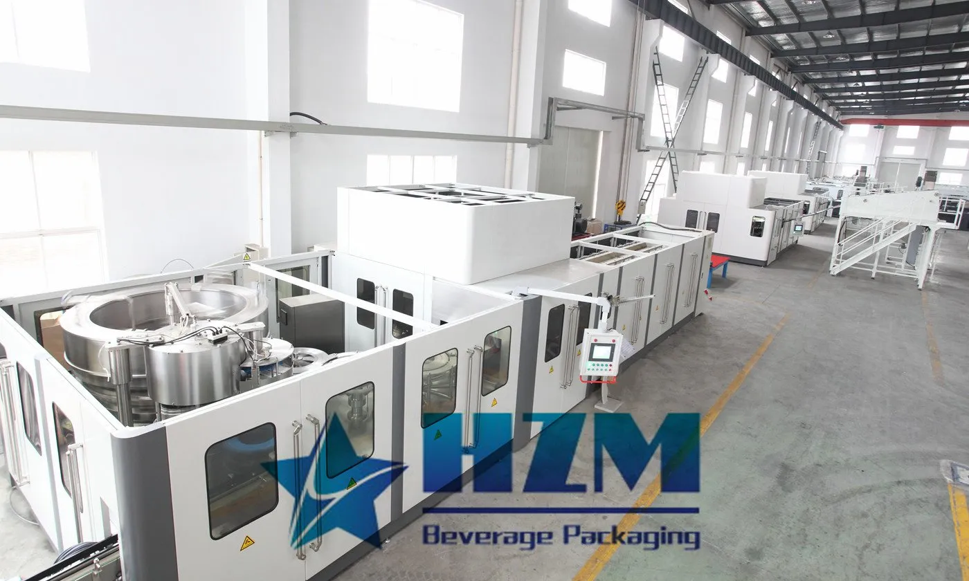
A blowing, filling and capping combiblock connects the operations directly. That may suit sustained demand for a defined package family, but it couples their stoppages and service requirements. Compare format flexibility, independent operation, layout and utilities rather than treating integration as automatically preferable.
What to inspect in a bottle trial
Collect samples by cavity and at different points in the run. Examine dimensions, neck condition, base formation and material distribution. Complete the mechanical and packaging checks required for the application, including closure fit and downstream handling. The acceptance plan should state the approved methods and limits.
If a defect repeats in one cavity, retain cavity identification in the records. If it appears across all cavities as conditions change, compare preform lots, heating stability, air supply and cooling. Preserve the approved process before making adjustments, and carry out machine work under the manufacturer’s service procedures.
For a production-rate trial, count acceptable bottles over a defined period and record rejects, replenishment and stops. A short burst of maximum mechanical speed does not establish the sustainable bottle supply available to the filler.
Build the enquiry around the complete bottle family
List every planned bottle with its volume, drawing, preform, closure and output target. State which format will run most often and which formats must be accommodated for future demand. Ask which moulds and change parts are included, how they are changed and what storage is needed.
Send HZM the package specifications, operating hours, utility conditions and the intended filling interface. This allows the bottle production machine to be selected as part of a working packaging system, with a documented route from preform supply to an acceptable filled bottle.
Talk to our engineering team
Need help planning your packaging line?
Share your product, bottle and capacity requirements for a practical equipment recommendation.