
Insights & Updates
How to Plan Safe Access for Beverage Production Line Installation and Maintenance
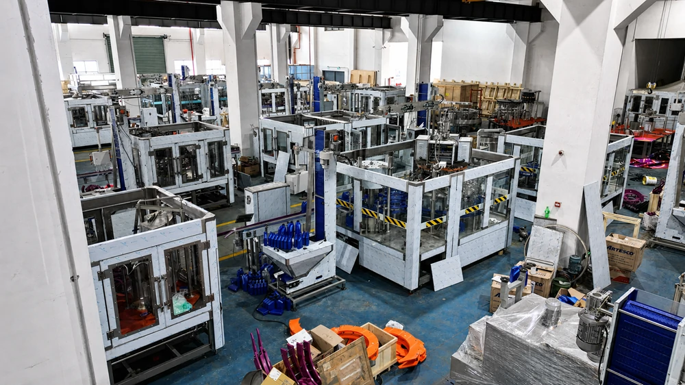
A beverage production line cannot be planned around output and process flow alone. Operators must be able to reach valves, instruments, tank manways, drive units and inspection points without climbing on pipes, conveyors or machine frames.
Access requirements should therefore be reviewed while the equipment layout is still being developed. Adding a walkway or staircase after the machinery has been installed is usually more expensive and may reduce aisle width, obstruct material movement or create new hygiene problems.
This is particularly important on complete beverage lines that combine water treatment, product preparation, bottle blowing, filling, labeling, conveying and secondary packaging in one workshop.
Identify Access Requirements Before Equipment Installation
The first step is to identify every component that requires routine operation, inspection, cleaning, adjustment or replacement. The frequency of access matters.
A valve operated every shift requires a different access arrangement from a pipe connection inspected once a year. Frequently used controls should be reachable from floor level or from a permanent working platform. Temporary access may be acceptable for infrequent maintenance, provided the method is safe and suitable for the location.
The layout review should cover:
- Tank manways, agitator motors and level instruments
- Filter housings and membrane components
- Dosing units and chemical tanks
- CIP supply and return connections
- Product pipe valves and sampling points
- Filling machine tanks and upper transmission components
- Label and packaging material loading positions
- Conveyor motors, sensors and transfer sections
- Cable trays, compressed-air pipes and utility headers
- Exhaust ducts and ventilation equipment
The review should also consider the tools, spare parts and lifting space required for maintenance. A technician may be able to reach a motor, for example, but still lack enough room to remove it safely.
Access Around Water Treatment Equipment
A water treatment system may include multimedia filters, activated carbon filters, softeners, cartridge filters, reverse osmosis membranes, UV sterilizers, ozone equipment and treated-water tanks.
Many of these components are accessible from floor level, but larger systems often require elevated access. Tank openings, automatic valve groups, upper pipe connections and instruments may be positioned above normal working height.
Access around water treatment equipment should allow operators to:
- Replace filter media and cartridges
- Inspect tank openings and internal components
- Service valves and actuators
- Remove RO membrane elements
- Calibrate flow, pressure and conductivity instruments
- Reach chemical dosing points without carrying containers up unsuitable ladders
The platform structure should not block drain channels or prevent the removal of large components. Sufficient clearance should also be left around pumps and membrane housings.
Platforms for Beverage Processing Areas
Juice, tea, flavored water and carbonated drinks require more processing equipment than a standard bottled-water line. A typical beverage processing system may contain sugar-melting tanks, blending tanks, filters, homogenizers, degassers, heat exchangers, CIP units and product storage tanks.
Large process tanks frequently have top-mounted agitators, spray balls, vents, level sensors and manways. These parts require safe access during inspection and maintenance.
Permanent platforms are usually the practical choice where operators work regularly. A properly designed platform should provide stable footing around the required operating points without interfering with pipework or tank insulation.
The position of the stairs also needs attention. Operators should not have to cross product hoses, steam pipes or wet drainage areas to reach the platform. Where ingredients are added manually, the access route must accommodate the weight and dimensions of the material being carried.
Manual lifting should be minimized. For larger ingredient bags or containers, a dedicated material-handling arrangement is preferable to carrying them up a staircase.
Access Above Filling and Packaging Lines
Modern beverage filling machines contain upper sections that may need periodic inspection, lubrication or part replacement. These can include the product tank, rotary distributor, capping transmission, electrical connections and service piping.
Routine operating controls should remain accessible from floor level whenever possible. A permanent platform may be required when regular access to the upper machine is unavoidable.
Conveyor crossings present another common layout issue. Workers should not step over running conveyors or move through guarded machine areas to reach the opposite side of a line. A properly positioned crossover platform or bridge can provide access without interrupting production.
The bridge must have enough clearance for bottles, packs and machine guards below it. Its support columns should not reduce the width of forklift routes, emergency exits or maintenance aisles.
Permanent and Temporary Access Are Not Interchangeable
Permanent platforms are intended for locations that require frequent access. They normally include stairs, handrails, guardrails, toe boards and a slip-resistant walking surface.
Temporary access equipment is used for construction, installation or occasional maintenance. Depending on the workshop and the work involved, this may include mobile scaffolding, a scissor lift or another approved elevated access system.
During factory construction or major building maintenance, certain overhead areas may not be reachable from a fixed walkway or mobile lift. A correctly selected suspended platform can provide temporary access to exterior walls, ceilings, elevated utility routes or other difficult locations. It is auxiliary access equipment and should not be treated as part of the beverage processing or filling system.
The access method must be selected according to the working height, available anchorage, floor condition, surrounding machinery and applicable safety requirements. Equipment should only be installed and operated by trained personnel in accordance with its operating instructions and local regulations.
Material Selection for Wet and Hygienic Areas
Platform materials should match the conditions inside the workshop. Beverage plants contain water, cleaning chemicals, product residues and areas with frequent washdown.
Stainless steel is commonly used near open product zones, processing tanks and filling equipment because it is corrosion-resistant and easier to clean. Galvanized or coated carbon steel may be suitable in dry utility areas, depending on the plant standard and local environment.
Regardless of material, the design should avoid:
- Surfaces that retain water or product residue
- Openings that allow tools or loose parts to fall onto equipment
- Corrosion points around welds and fasteners
- Sharp edges near operating positions
- Hollow sections that cannot be sealed or cleaned
- Supports that block floor drainage
- Horizontal ledges that collect dust
- Flaking paint above bottles or exposed packaging materials
Walking surfaces should provide grip when wet while remaining practical to clean. Platform drainage must not discharge onto electrical cabinets, motors, open containers or pedestrian routes.
Keep Structures Away From Open Product Zones
A platform should not be positioned directly above exposed product, open bottles, caps or filling valves unless the production process specifically requires it and suitable hygiene controls are provided.
Foot traffic above an open filling area can introduce dust, water, loose fasteners and other contaminants. Maintenance work creates an additional risk because tools, lubricant or metal particles may fall into the production zone.
Where overhead access is unavoidable, the layout may require closed floor panels, protective covers, controlled maintenance procedures or production shutdown before work begins. The exact arrangement depends on the hygiene level of the line and the type of beverage being produced.
Coordinate Platforms With Utilities and Cleaning Systems
Access structures must be coordinated with process pipes, electrical trays, compressed-air lines, ventilation ducts and drainage. Designing these systems separately often leads to conflicts during installation.
Common problems include:
- A staircase blocking a control cabinet door
- A platform support installed over a drain
- Handrails interfering with pipe insulation
- Utility pipes reducing headroom above a walkway
- Cable trays preventing removal of a motor
- CIP hoses crossing stairs or operating aisles
- Platform legs occupying the bottle or packaging route
A coordinated layout should show both the equipment footprint and the space needed to operate, clean and service each machine. It should also account for future bottle formats, additional tanks or possible increases in production capacity.
Maintain Clear Working and Emergency Routes
Access platforms should improve movement through the plant, not create new obstructions. Main aisles, emergency exits, fire equipment and electrical isolation points must remain clear.
The layout should separate personnel routes from forklift and pallet movement wherever practical. Stairs should not end directly in a vehicle route. Doors, guard panels and machine components must be able to open fully without blocking a walkway.
Lighting is another practical consideration. Operators need enough light to read instruments, inspect pipe connections and work safely on upper levels. Emergency lighting may also be required depending on the plant design and local regulations.
Inspect Platforms as Part of Plant Maintenance
Platforms, stairs and guardrails are often treated as static building components and receive less attention than production machinery. They still require periodic inspection.
The maintenance team should check:
- Structural connections and anchor points
- Welds, bolts and fasteners
- Guardrails, handrails and toe boards
- Stair treads and walking surfaces
- Corrosion or coating damage
- Water accumulation and drainage
- Vibration caused by nearby machinery
- Clearance around pipes and electrical systems
- Unauthorized modifications
Any structure affected by equipment relocation, pipe changes or building work should be reviewed again. A small modification can alter the load, reduce clearance or weaken a protective barrier.
Information Required for Layout Planning
Before developing the final line layout, the equipment supplier should receive accurate information about the workshop and the planned production process.
Useful project information includes:
- Workshop length, width and clear height
- Column positions and structural limitations
- Door and emergency-exit locations
- Floor level, drainage and load capacity
- Beverage type and production process
- Bottle or container specifications
- Required production capacity
- Water, power, steam and compressed-air connections
- Existing tanks, machines and utility pipes
- Local operating and maintenance practices
For a complete water filling production line, the layout should cover the full route from water treatment and bottle production to filling, labeling, packing and finished-product handling. Reviewing service access at this stage reduces installation changes and makes future maintenance more predictable.
Final Considerations
Safe access is part of production-line engineering. It affects installation, cleaning, maintenance time, hygiene control and the daily work of plant operators.
Permanent platforms should be provided where regular operation or maintenance takes place above floor level. Temporary access equipment should be reserved for suitable construction and infrequent maintenance tasks. Neither option should obstruct production flow, drainage, emergency routes or sanitation procedures.
HZM Machinery provides equipment layout and utility-planning support for water, juice, carbonated drink and other beverage production lines. To prepare a practical proposal, provide the beverage type, container specifications, target capacity and workshop drawing. These details allow the equipment arrangement, operating space and maintenance access to be considered together.
Talk to our engineering team
Need help planning your packaging line?
Share your product, bottle and capacity requirements for a practical equipment recommendation.
2023-12-06
An Easy-to-Understand Maintenance Plan for Beverage Packaging Machines
As the beverage industry continues to evolve, the smooth operation of beverage packaging machines is crucial for the efficiency of production lines.
Learn more
2023-06-29
Design, Installation, Commissioning, Production, and Maintenance of a Water Bottle Filling Line
The design, installation, commissioning, production, and maintenance of a water bottle filling line typically involve the following steps and considerations:
Learn more
2023-03-24
12,000BPH Carbonated Drinks Beverage Production Line in Installation
HZM customer checked the serveal our projects in East Europe and they’re very satisfied with the machine performance. So they ordered a 12,000BPH carbonated drinks beverage production line from HZM. It includes DXGF32-32-8 carbonated drinks filling machine, Bopp labeling machine, PE film shrink packing machine, bottle dryer and conveyor system. After 2months shipment and customs […]
Learn more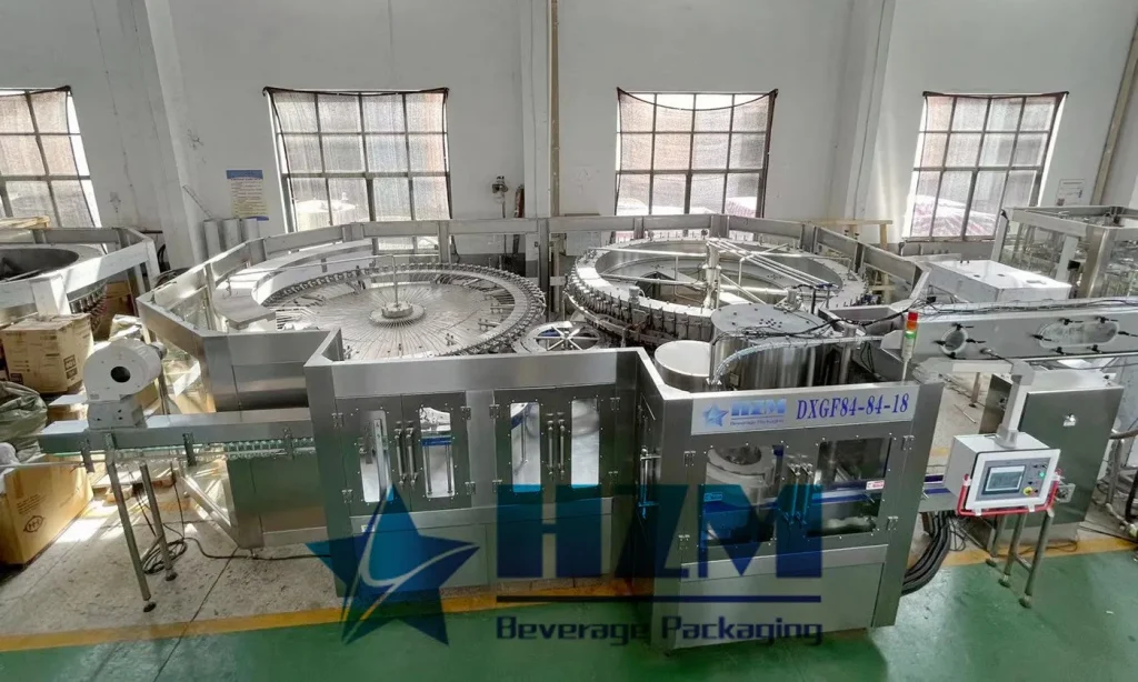
2023-08-17
Purchasing Plan for Carbonated Drink Filling Machine
In the beverage production industry, acquiring a suitable Carbonated Drink Filling Machine is a critical decision that ensures efficient operation of the production line and product quality
Learn more2023-07-04
Water Filling Production Line: Efficient, Safe, and Stable Industry Solution
water filling production line is a crucial equipment in the modern chemical industry, used for efficient, safe, and stable filling and packaging of water or other liquid products. This article will provide a detailed overview of the structure, characteristics, advantages, production standards, and safety measures of the water filling production line. It aims to help readers gain a comprehensive understanding of the importance and application of this industry solution.
Learn more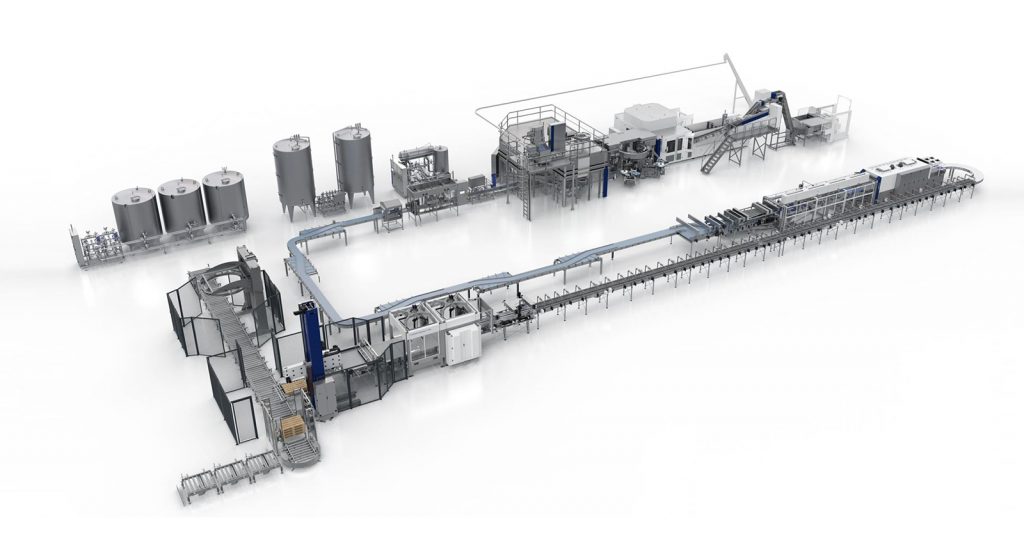
2023-09-18
Comprehensive Equipment Plan for Mineral Water Production
This plan outlines the key components and processes for setting up a mineral water production line, focusing on equipment selection, workflow optimization, quality assurance, and sustainability.
Learn more