Equipment
Reverse Osmosis Water Treatment
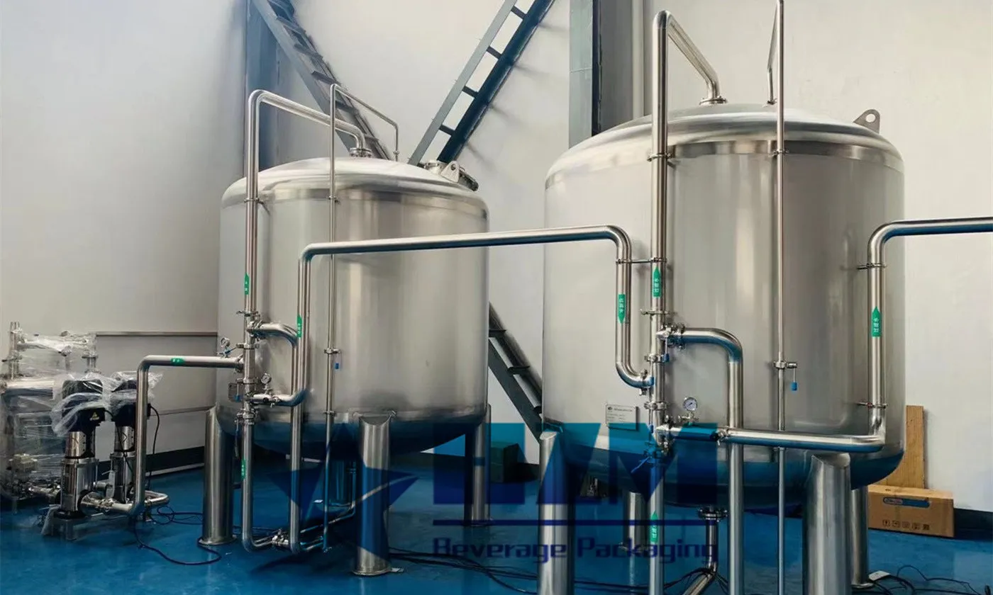
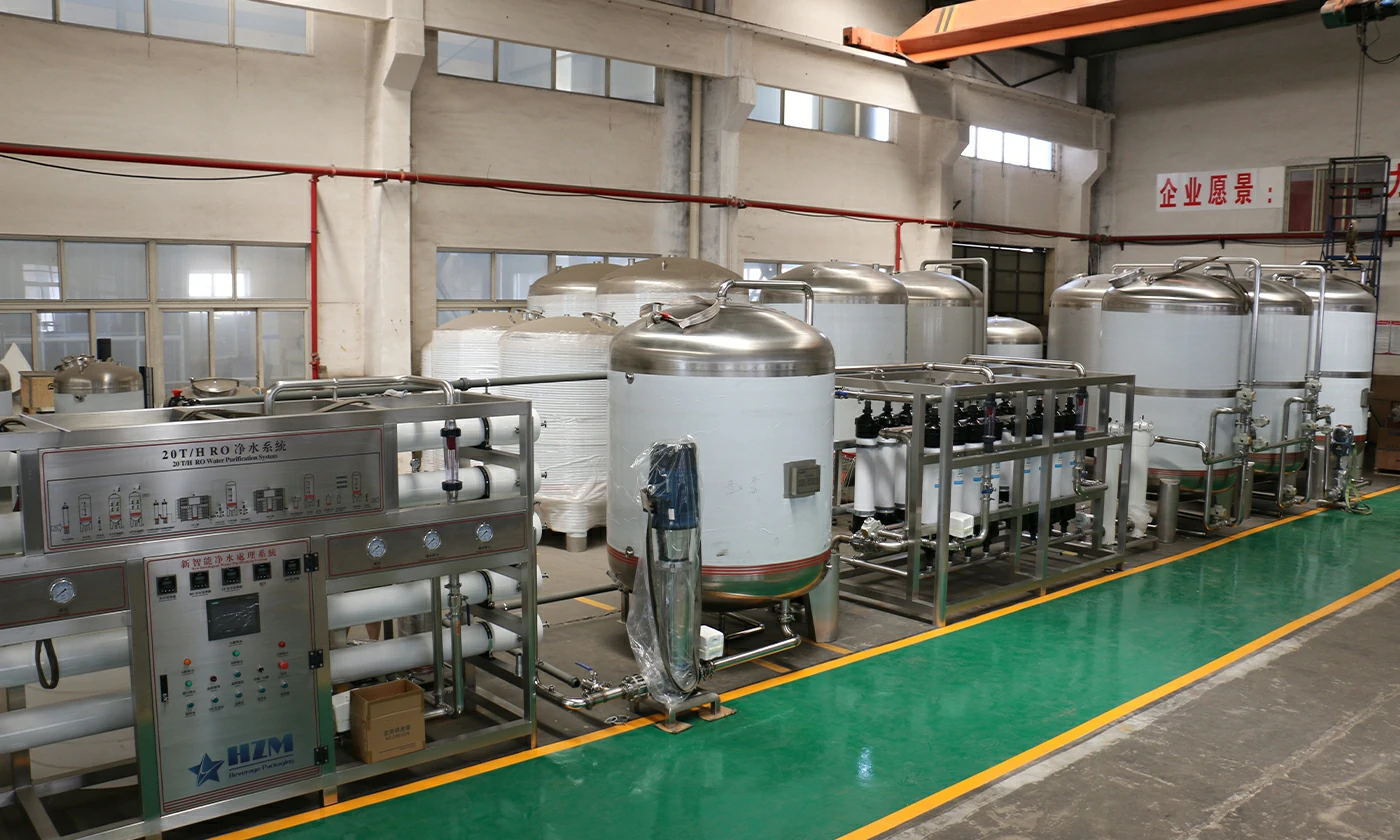
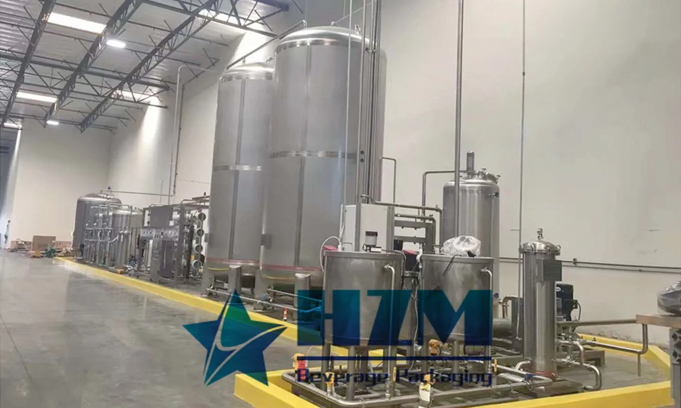
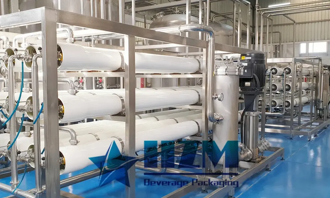
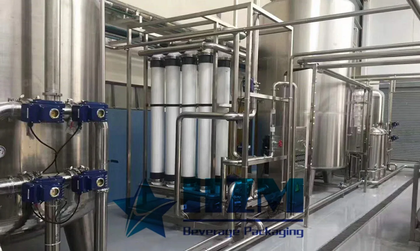
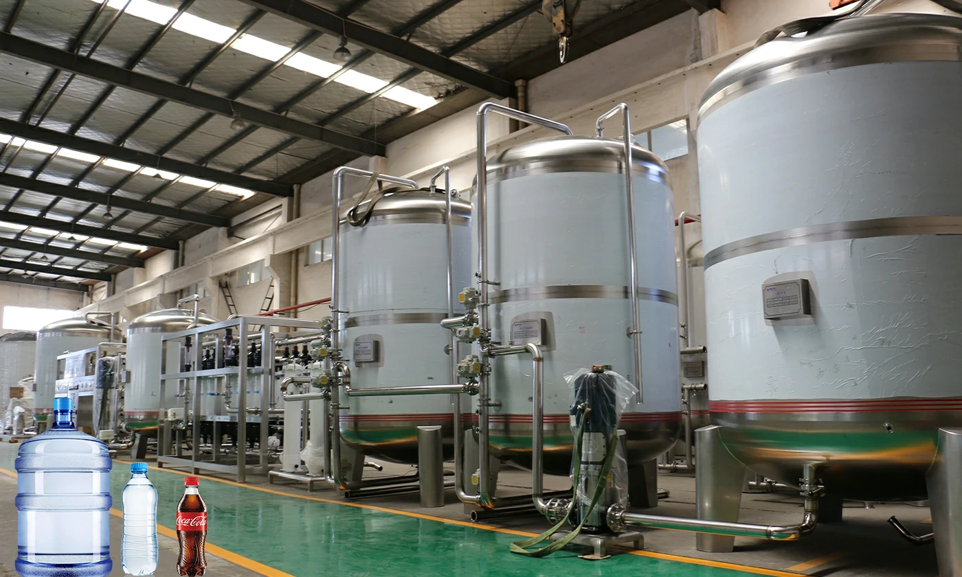
The reverse osmosis system treats water for bottled-water and beverage production.
Learn more
Tip: You can request pricing for individual machines or a complete production line solution.
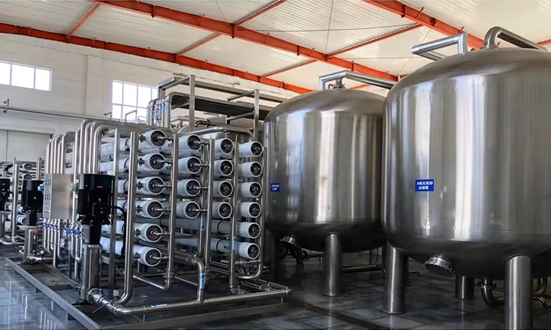
An RO bottling-water plant is selected from the source analysis and the water required by the bottle schedule. HZM evaluates net permeate output, treatment losses, storage and final delivery to the filling section under the agreed site conditions.
An RO water treatment machine for bottled water production should be sized around the quantity and quality of water that must reach the filler. The correct design links raw-water pretreatment, membrane separation, permeate storage and the final supply circuit. HZM evaluates these stages together so that a bottling plant can maintain the specified water quality during normal running, peak demand and restart.
RO is particularly relevant when a purified-water specification calls for dissolved-salt reduction. It is not automatically the correct process for water marketed around its natural mineral composition. Before selecting equipment, identify the intended product category, the applicable finished-water requirements and any permitted treatment restrictions.
For purified bottled water, provide target chemical and microbiological limits alongside the source-water report. If mineral adjustment is part of the approved product design, it must be specified as a separate controlled operation. It should not be assumed to be included in a standard RO skid.
Use water in bottles, litres/hour = bottles/hour × litres/bottle. The examples below show how bottle volume changes the demand on the water-treatment system.
| Example bottling schedule | Water entering bottles | What remains to be added |
|---|---|---|
| 12,000 bottles/hour × 0.5 litre | 6,000 litres/hour | Rinsing, cleaning and other treated-water users |
| 8,000 bottles/hour × 1 litre | 8,000 litres/hour | The same auxiliary uses, calculated for this format |
| 5,000 bottles/hour × 1.5 litres | 7,500 litres/hour | Auxiliary uses and the actual production schedule |
The bottle format with the highest bottle count is not necessarily the format with the highest water demand. Check the complete schedule, including periods when the treatment plant is cleaning or filters are backwashing. Size usable storage from the duration of a supply-demand mismatch rather than selecting a tank simply because it is larger than the hourly flow.
HZM offers a 10 T/H RO water treatment system with a capacity of 10,000 litres/hour and SUS304/SUS316 material options. Net permeate output is specified for the feed-water quality and temperature at your plant.
| Quotation item | Basis for this application |
|---|---|
| Treatment capacity | 10 T/H (10,000 litres/hour) |
| Required net permeate output | Calculated from bottle demand, auxiliary uses and operating hours |
| Pretreatment | Selected for source-water solids, scaling tendency and other relevant contaminants |
| Recovery and concentrate flow | Defined by membrane-system design and feed chemistry |
| Water-contact materials | Confirmed component by component for the water and cleaning process |
| Final treatment and storage | Selected to maintain the approved water specification through to filling |
Feed temperature, dissolved-solids concentration, pressure and membrane condition affect the available permeate output. Compare proposals using the same feed-water analysis and operating basis. A quotation based on favourable feed conditions may not describe the seasonal conditions at the intended site.
Recovery is the proportion of feed that becomes permeate. Increasing recovery also concentrates the substances left on the feed side, so it cannot be selected independently of scaling and fouling risks. Require a stated feed, permeate and concentrate water balance. This is also the basis for sizing the raw-water supply and the concentrate discharge route.
Once treated water enters a tank and pipework, the condition of that downstream system becomes part of product quality. Review tank ventilation, cleanability, drainability, sampling access and the route to the filler. Long idle periods and unused branches deserve attention in the sanitation plan.
The chosen final treatment must be compatible with the product, contact materials and permitted process. Establish how the tank and distribution circuit are cleaned, what happens after extended shutdown and who authorises return to production. A low outlet conductivity is not a substitute for these controls.
The automatic water bottle filler requires a stable supply during production. Define storage level signals, low-water responses and the sequence for starting and stopping the treatment and filling sections. Avoid repeatedly stopping the filler because the tank reaches its low level under the largest-volume bottle schedule.
At acceptance, check net output, the approved water-quality criteria, instrument readings, alarm behaviour and the agreed restart sequence. Use the intended feed water or document the differences between factory test water and site water so the acceptance results are interpreted correctly.
Only the simple bottle-water calculation gives that number for a 500 ml format. It excludes other water uses and assumes the plant can deliver the stated net permeate continuously under site conditions. A full water balance is required.
They can be assessed for material compatibility, usable capacity, hygiene, vents, drainage and connection layout. An existing tank should not be accepted solely because its volume is sufficient.
Provide seasonal source-water analysis where available, bottle sizes and outputs, cleaning demand, intended water specification, operating hours, storage details and the building plan. These allow HZM to match RO treatment to the bottling operation.
Talk to an engineer
Send your capacity, bottle specification and beverage type for a complete proposal.
Equipment
The reverse osmosis system treats water for bottled-water and beverage production.
Learn moreEquipment
The RO water treatment plant produces purified water through feed-water pretreatment and reverse-osmosis membrane separation.
Learn moreEquipment
10 T/H RO water treatment for ingredient, process and rinse water in food and beverage plants.
Learn moreEquipment
10 T/H reverse osmosis water treatment for food and beverage production, with pretreatment and stainless-steel equipment options.
Learn moreEquipment
1,000 litres/hour reverse osmosis water treatment for bottled-water, beverage and food production.
Learn moreEquipment
This RO water treatment system combines pretreatment, reverse-osmosis membrane separation and final treatment for purified-water production.
Learn moreEquipment
HZM water treatment systems prepare process water for bottled water, beverages and brewing.
Learn moreEquipment
This industrial drinking-water treatment system supplies treated water to bottling and beverage plants.
Learn moreEquipment
10 T/H bottled-water treatment with pretreatment, reverse osmosis, storage and connections to the water filling line.
Learn moreSolution & application
 Complete production line
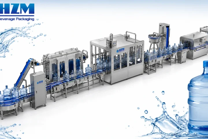
3-5 Gallon Water Production Line
Explore solution →
Complete production line
3-5 Gallon Water Production Line
Explore solution →
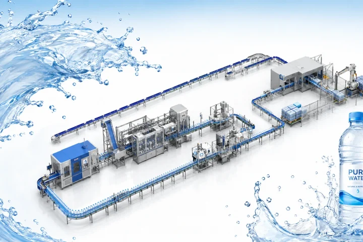 Complete production line
Bottled Water Production Line
Explore solution →
Complete production line
Bottled Water Production Line
Explore solution →
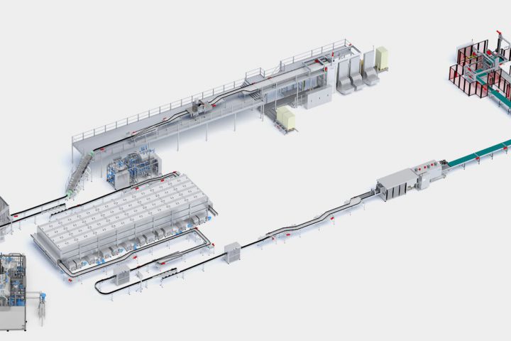 Complete production line
Cans Filling Production Line
Explore solution →
Complete production line
Cans Filling Production Line
Explore solution →
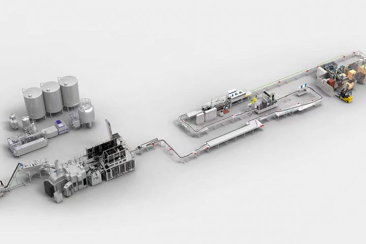 Complete production line
CSD Filling Production Line
Explore solution →
Complete production line
CSD Filling Production Line
Explore solution →
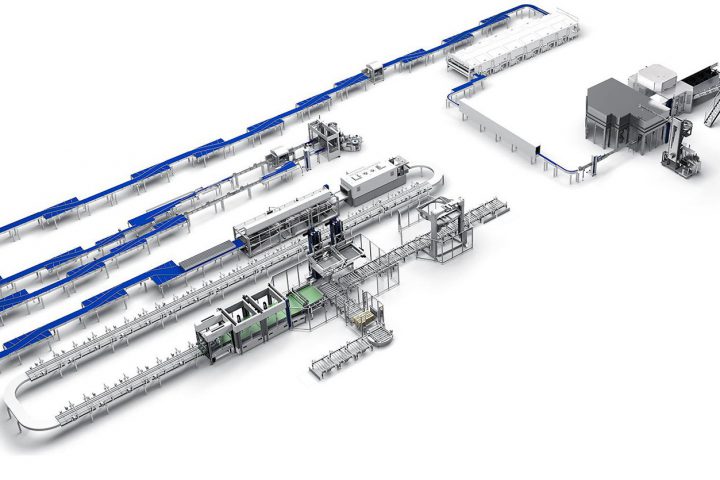 Complete production line
Juice Filling Production Line
Explore solution →
Complete production line
Juice Filling Production Line
Explore solution →
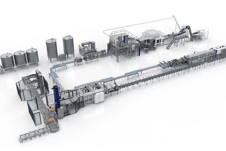 Complete production line
Water Filling Production Line
Explore solution →
Complete production line
Water Filling Production Line
Explore solution →
Build your production line
Tell us your beverage, container, capacity and target market. Our engineering team will prepare a practical line proposal.