
Insights & Updates
Bottled water treatment system
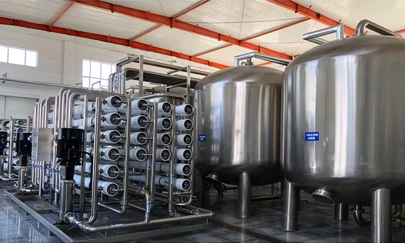
A bottled water treatment system should be selected from a water analysis, a finished-product specification and a production schedule. Choosing a filter or RO plant from its advertised litres per hour alone can leave a factory with adequate flow but unsuitable water, or good water quality that cannot be maintained when the filler and cleaning system operate together.
The treatment equipment also needs to be considered alongside storage and filling. If the water is acceptable at the treatment outlet but deteriorates in a tank or distribution branch, increasing membrane capacity will not solve the problem. The useful design boundary extends from the source to the closed bottle.
Define the bottled-water product first
Purified water, natural mineral water and other drinking-water categories can have different process and composition requirements. RO may be appropriate when dissolved-salt reduction is required. It should not be assumed suitable where the product must retain its natural mineral characteristics.
Write down the target water quality and the applicable product requirements. Include relevant chemical, microbiological and sensory criteria and the sampling locations used for acceptance. “Drinking water quality” without an identified standard or test plan is too vague for a reliable equipment specification.
Read the analysis as a design document
| Information | Why it matters | What it can change |
|---|---|---|
| Turbidity and suspended matter | Indicate particle loading | Pretreatment and filter service requirements |
| Hardness, alkalinity and relevant ions | Help assess scaling tendency | Softening, dosing strategy and membrane recovery |
| Iron and manganese | Can affect appearance, deposits and treatment performance | Targeted pretreatment and monitoring |
| Conductivity and dissolved-solids composition | Describe the dissolved ionic load | Purification duty and membrane-system design |
| Microbiological results | Help define source and handling risks | Permitted treatment, hygienic controls and release testing |
| Temperature and seasonal variation | Influence equipment performance and design conditions | Capacity basis and operating allowance |
Include the water source, collection method and any treatment already applied. A laboratory result without that context can be difficult to interpret. If the water supply changes during the year, provide representative results rather than selecting only the most favourable sample.
Give every treatment stage a job
Media filtration can remove appropriate suspended material; selected adsorption or dechlorination stages address different concerns. Softening and scale-control measures serve another purpose. RO provides a membrane-separation stage where the water specification requires it. These functions should be matched to the actual analysis instead of assembled as an identical equipment list for every source.
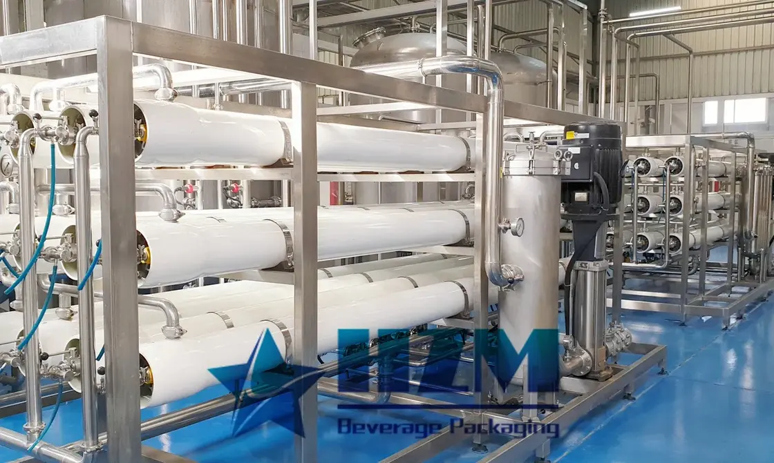
An HZM RO water treatment system can combine membrane separation with a water pretreatment system selected for the source water. Define the contaminant or operating condition each stage must control and the measurements used to check its performance.
Keep feed, permeate and concentrate flow distinct
An RO water balance separates the water entering the membrane system from the permeate available for production and the concentrate leaving it. Recovery is the permeate share of the feed. It affects raw-water demand and concentrate flow as well as the membrane operating conditions.
For a sizing example, producing 10 cubic metres/hour of permeate at an assumed 75% recovery requires about 13.3 cubic metres/hour of membrane feed and produces about 3.3 cubic metres/hour of concentrate. Use the recovery specified for the source water and membrane design when calculating the actual plant water balance.
Filter backwash, cleaning and other water uses may add further raw-water demand. Keep them visible in the plant water balance rather than hiding them inside the nominal capacity figure.
Match treatment to the production schedule
The HZM 10 T/H RO treatment system has a capacity of 10,000 litres/hour. When evaluating a system of that capacity, calculate the water entering bottles for every planned format and add simultaneous process uses. State the temperature and source-water conditions under which net output must be achieved.
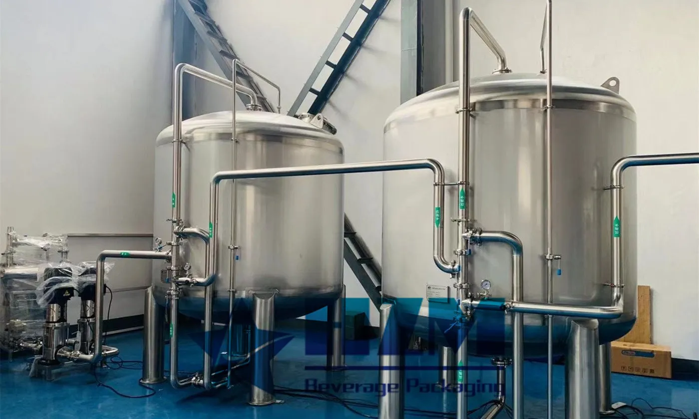
Storage can bridge a temporary peak if the plant can replenish the tank between demand periods. A persistent deficit means the treatment capacity, production schedule or both need to change. An oversized tank with a long water residence time can create its own operating and hygiene problems.
Investigate where quality or flow is being lost
If flow falls, compare the current operating data with the commissioning baseline. Check feed conditions and instrument reliability before deciding that the membrane needs replacement. Differential pressure helps locate a restriction, while conductivity and flow trends provide different information about membrane-system behaviour.
If a microbiological result is unacceptable, compare the source, treatment outlet, storage outlet and finished bottle under the plant’s sampling procedure. A problem appearing only after storage points to a different investigation from one already present in the feed. Hold affected production according to the site’s quality procedures and investigate the actual pathway.
Changes to cleaning chemicals, membrane settings or treatment sequence should follow the equipment and process specifications. Increasing chemical strength or operating pressure without identifying the cause can damage equipment or complicate the investigation.
Make acceptance and handover specific
The acceptance plan should state net output, feed conditions, water-quality criteria, measurement methods and the locations where samples are taken. Include the operating response to low feed, low tank level and any quality alarm provided in the agreed design.
At handover, obtain the process diagram, equipment and consumables list, operating instructions, cleaning procedures and baseline readings. Operators need a clear start-up and shutdown sequence and a defined process for releasing water after cleaning or extended downtime.
Prepare an enquiry that can be engineered
Send HZM the raw-water analysis, product category, finished-water specification, bottle-size schedule, required output, operating hours, site layout and utility conditions. Include existing tanks and pipework if they are to be reused. This allows the treatment system to be selected for the bottling operation and its quality requirements, with clear supply and acceptance boundaries.
Talk to our engineering team
Need help planning your packaging line?
Share your product, bottle and capacity requirements for a practical equipment recommendation.
Equipment
Water Treatment System
HZM water treatment systems prepare process water for bottled water, beverages and brewing.
Learn more
Equipment
Industrial Drinking Water Treatment System
This industrial drinking-water treatment system supplies treated water to bottling and beverage plants.
Learn more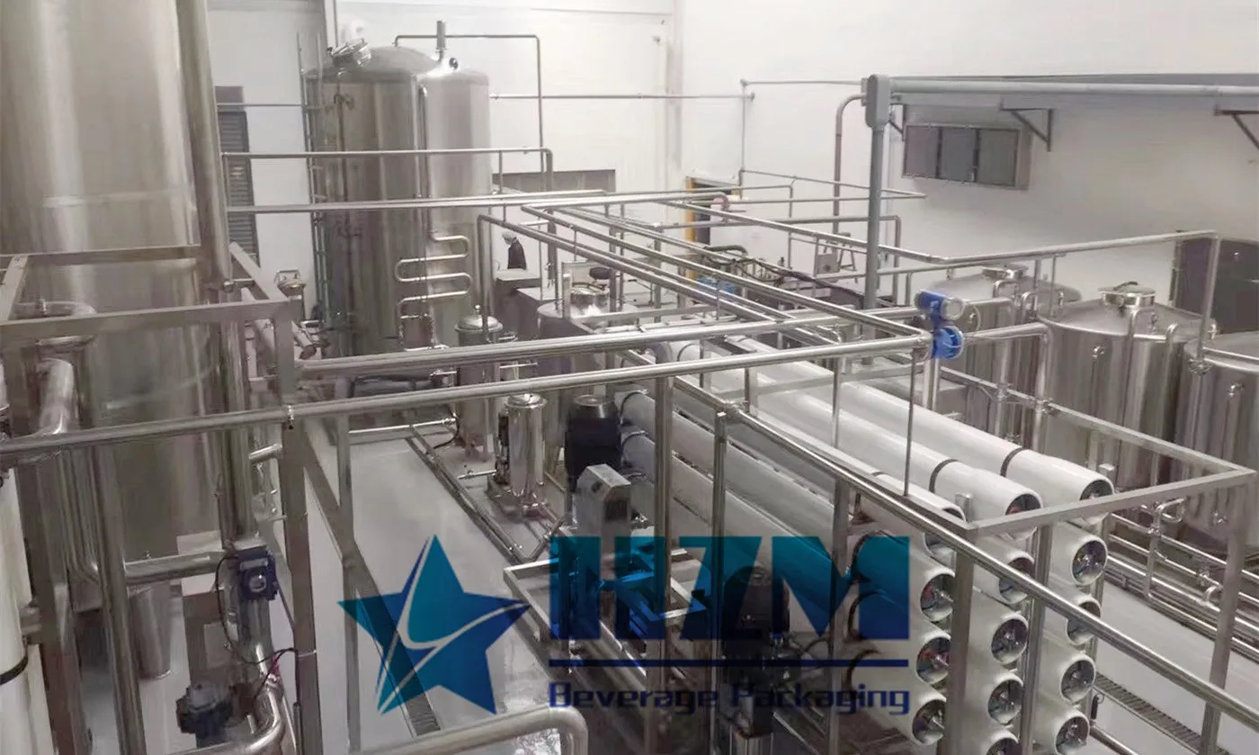
Equipment
Water Treatment Machine Purification System
HZM water purification equipment combines filtration, membrane treatment and final treatment in one process.
Learn moreEquipment
RO Water Treatment Machine for Bottled Water Production
10 T/H reverse osmosis water treatment for purified-water bottling, with pretreatment, storage and filler-supply connections.
Learn moreEquipment
RO System Water Treatment Plant
The RO water treatment plant produces purified water through feed-water pretreatment and reverse-osmosis membrane separation.
Learn moreEquipment
Reverse Osmosis Water Treatment
The reverse osmosis system treats water for bottled-water and beverage production.
Learn moreEquipment
Industrial food water treatment equipment – 10T/H RO Water Treatment System
10 T/H reverse osmosis water treatment for food and beverage production, with pretreatment and stainless-steel equipment options.
Learn more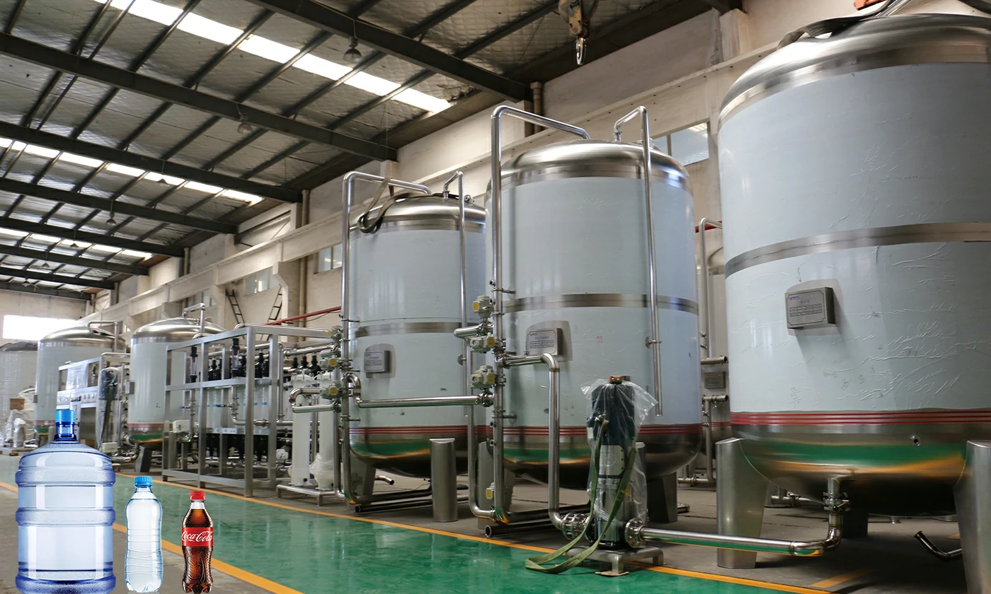
Equipment
bottled water treatment plant – water purification system for bottling line
10 T/H bottled-water treatment with pretreatment, reverse osmosis, storage and connections to the water filling line.
Learn moreEquipment
Water Treatment for the Food & Beverage Industry – RO Water Treatment Equipment
10 T/H RO water treatment for ingredient, process and rinse water in food and beverage plants.
Learn more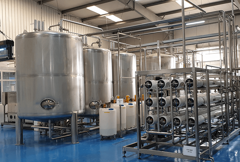
2023-03-24
Why is Water Treatment System Important?
Water is important for our existence. Seventy percent of our body depends on water. We have to take at least 13 glasses of water in a day. In this way, we will stay healthy and active. Drinking water is important, yet we only have to drink purified water. The water coming from the taps of […]
Learn more
2023-03-24
The Overview of Water Treatment Systems in Filling Systems
We have been drinking pure water for many years, so it is conceivable that this bucket of pure water is used to install equipment for purifying pure water. It takes some systematic processes to get our drinking water standards. The raw water can be obtained through several parts of the pretreatment system, reverse osmosis system, […]
Learn more
2023-03-24
What is the Working Principle of Water Treatment Equipment?
Today, Water purifiers have become a need for almost every home. It is a form of water treatment machine that helps to get water clean and safe for drinking. This way, it ensures that you are protected from several forms of water-borne diseases. Water treatment processes are of different types and include Ultra Filtration (UF), […]
Learn more
2023-03-24
Why Do We Need Water Treatment?
Water treatment is the process for enhancing the quality of water so that it meets the water quality criteria for its fitness for the intended use after having been chemically or biological polluted. Treated water has great importance in industrial applications as well as safe drinking. Water treatment protects humans and ecosystem Water contains elements toxic […]
Learn more
2023-03-24
Main Process of Drinking Water Treatment System
There are certain characteristics that beverages require, such as sufficient mineral content, flavor, pH balance to create high-quality drinking products with an acceptable taste. The water treatment systems are designed to generate these characteristics that are required for these drinks. Ultimately, the main component of all beverages is water, and the quality of the water […]
Learn more2026-07-24
Drinking Water Treatment System Design: Process, Equipment and Selection
A buyer's guide to drinking water treatment systems, from raw-water analysis and pretreatment to RO, disinfection, storage, sanitation, sizing and operating cost.
Learn more