
Insights & Updates
RO CIP Did Not Restore Performance: Why Cleaning Fails
When ineffective cleaning of RO membrane elements appears, changing the nearest setpoint is tempting but risky. A durable repair starts by retaining samples, capturing the first alarm and separating a local head or lane problem from a line-wide process problem.
Water-treatment performance must be evaluated with normalized operating data. Raw-water changes, temperature, recovery, pressure, flow and conductivity interact; a single gauge reading is not enough to identify membrane damage or fouling. The objective is not merely to clear the alarm for ineffective cleaning of RO membrane elements, but to recover a repeatable, verifiable process.
Quick answer: Cleaning fails when the foulant is misidentified, flow is too low, pH or temperature is wrong, the solution is exhausted, vessels are cleaned in the wrong grouping, or damage is irreversible. Review the full cleaning record.
What operators usually see
Use the following signs to define the boundary of the problem. A head-by-head, lane-by-lane or time-based pattern is especially valuable: For this case, preserve evidence that shows whether normalized flow changes little after CIP.
- Normalized flow changes little after CIP
- Pressure drop improves but salt passage worsens
- Cleaning solution becomes dirty immediately
- Performance recovers and then deteriorates within days
Make the equipment safe and protect the product
Use the plant chemical-handling procedure, suitable PPE and lockout/tagout. Depressurize housings and verify that cleaning chemicals have been displaced before opening a pump, filter or membrane vessel.
Trend feed, concentrate and permeate flows; stage pressures; differential pressure; conductivity; temperature; pH; oxidant residual; and recovery. Compare normalized values with the accepted commissioning baseline. Explicitly record whether normalized flow changes little after CIP.
Most likely causes, in practical checking order
1. Wrong cleaner for the foulant
Acid, alkaline, chelant and surfactant approaches address different deposits and cannot be chosen by guesswork To test this explanation without guessing, compare normalized pre-clean and post-clean flow, pressure drop and salt passage Record the result before moving to the next cause.
2. Insufficient crossflow
Low pump capacity or too many vessels in parallel fails to sweep loosened material out A practical confirmation step is to review foulant evidence, feed analysis and membrane supplier guidance. Compare the finding with a known-good run.
3. Uncontrolled pH, temperature or exposure
The actual solution at the membrane differs from the prepared tank Do not compensate for this condition in the recipe. First, verify cleaning flow per vessel, return pressure and absence of permeate backpressure Keep the original setting and measured result in the fault record.
4. Irreversible damage or compaction
Oxidation, abrasion, telescoping or severe deposits cannot be repaired by cleaning Separate this cause from the others with one controlled check: trend solution pH, temperature and appearance through each step Use the same product, format and speed for the comparison.
Step-by-step diagnostic procedure
Follow the sequence in order and preserve each result. Stop if any check would require defeating a guard, interlock or validated food-safety control.
- Compare normalized pre-clean and post-clean flow, pressure drop and salt passage
- Review foulant evidence, feed analysis and membrane supplier guidance
- Verify cleaning flow per vessel, return pressure and absence of permeate backpressure
- Trend solution pH, temperature and appearance through each step
- Confirm tank volume, dilution and cleaner concentration
- Inspect representative elements when data indicates physical or chemical damage
Corrective actions that address the root cause
The repair must remove the mechanism, not hide its alarm. Use specified hygienic and safety-rated parts and record every change.
- Repeat cleaning only when data supports a corrected chemistry or hydraulic condition
- Clean stages or vessel groups at the required crossflow
- Control solution pH and temperature at the return, not only in the tank
- Replace irreversibly damaged elements and remove the upstream cause
How to verify the repair before full-speed production
A successful no-load cycle is not enough. Use the actual product and package, sample every relevant head or lane, and verify this condition: Confirm that ineffective cleaning of ro membrane elements is absent for multiple consecutive cycles, not only for one sample. Review the alarm history and keep diagnostic product segregated until the site’s quality procedure releases it.
- Confirm that ineffective cleaning of ro membrane elements is absent for multiple consecutive cycles, not only for one sample.
- Compare the repaired result for “Normalized flow changes little after CIP” with the approved quality limit and the last known-good baseline.
- Check adjacent stations and downstream package quality for side effects associated with wrong cleaner for the foulant.
- For “RO CIP Did Not Restore Performance: Why Cleaning Fails”, record the final settings, measurements, parts used and restart authorization.
Prevent the problem from returning
Use the repair evidence to improve the control plan. The following actions make recurrence visible early:
- Trigger cleaning before severe irreversible loss
- Keep complete cleaning trend records
- Size and maintain the CIP pump for the actual vessel grouping
- Analyze deposits when recurrence is unexplained
- Train operators on membrane chemical and temperature limits
When to stop troubleshooting and call a specialist
Stop and contact the machine or component supplier when ineffective cleaning of ro membrane elements cannot be isolated with non-invasive checks, when it returns after an approved repair, or when calibration requires protected service tools. Specialist support is also required when the same protective fault returns after an approved repair or structural damage is suspected. Send the service engineer the fault history, photos, samples, trend data, recipe revision and work already completed.
Relevant equipment for this application
For a project-level comparison related to ineffective cleaning of RO membrane elements, see HZM Machinery’s Industrial Drinking Water Treatment System. Use actual product, container and utility data when evaluating whether the configuration fits the duty.
Frequently asked questions
What should be checked first when ineffective cleaning of RO membrane elements?
Cleaning fails when the foulant is misidentified, flow is too low, pH or temperature is wrong, the solution is exhausted, vessels are cleaned in the wrong grouping, or damage is irreversible. Review the full cleaning record. Preserve the original settings and take representative samples before repair work begins.
How can we distinguish wrong cleaner for the foulant from insufficient crossflow?
Acid, alkaline, chelant and surfactant approaches address different deposits and cannot be chosen by guesswork In contrast, low pump capacity or too many vessels in parallel fails to sweep loosened material out Compare the two mechanisms under the same operating condition by completing these checks: compare normalized pre-clean and post-clean flow, pressure drop and salt passage Then review foulant evidence, feed analysis and membrane supplier guidance
Can production continue while ineffective cleaning of RO membrane elements?
Only when the plant’s documented risk assessment and quality procedure allow it. For ineffective cleaning of RO membrane elements, stop and segregate production when package integrity, sanitation, validated processing, pressure safety, electrical protection or an uncontrolled reject trend is involved.
What evidence will help the equipment supplier respond faster?
Provide the model and serial number, product and format, target speed, first fault, timestamps, photos or video, affected station pattern and maintenance history. For this issue, also include normalized flow changes little after CIP and the measured result from this check: inspect representative elements when data indicates physical or chemical damage
Talk to our engineering team
Need help planning your packaging line?
Share your product, bottle and capacity requirements for a practical equipment recommendation.
Equipment
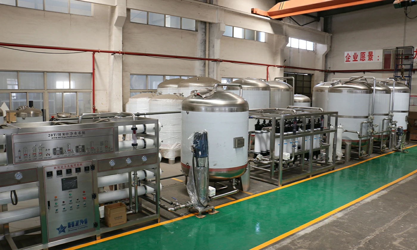
Industrial RO Drinking Water Treatment Plant – Reverse Osmosis Equipment for Beverage & Bottled Water
1,000 litres/hour reverse osmosis water treatment for bottled-water, beverage and food production.
Learn more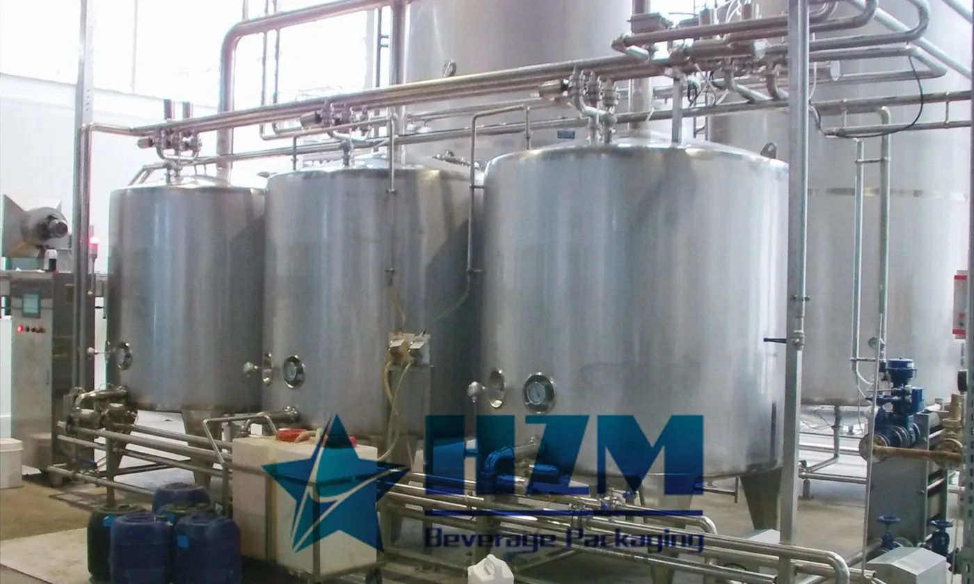
Equipment
CIP System
The CIP system cleans the internal surfaces of beverage tanks, pipelines and filling equipment without routine disassembly.
Learn more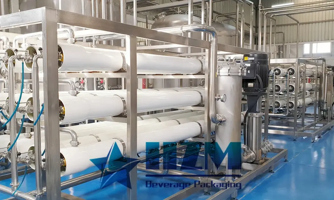
Equipment
Water Treatment System
HZM water treatment systems prepare process water for bottled water, beverages and brewing.
Learn more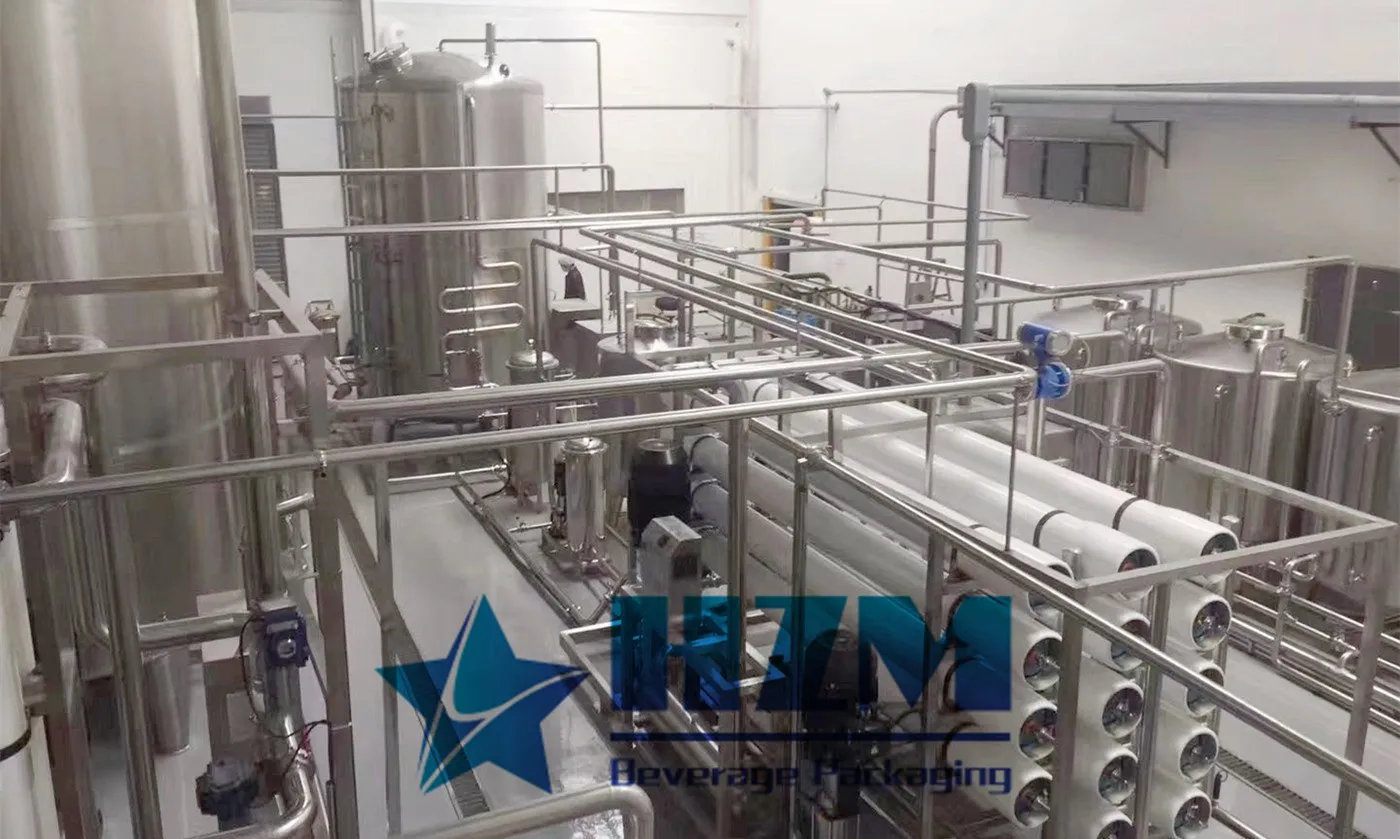
Equipment
Water Treatment Machine Purification System
HZM water purification equipment combines filtration, membrane treatment and final treatment in one process.
Learn more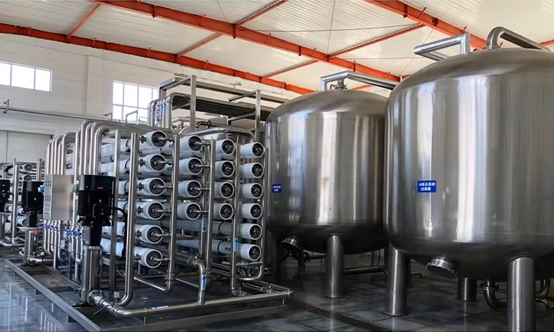
Equipment
Reverse Osmosis Water Treatment
The reverse osmosis system treats water for bottled-water and beverage production.
Learn more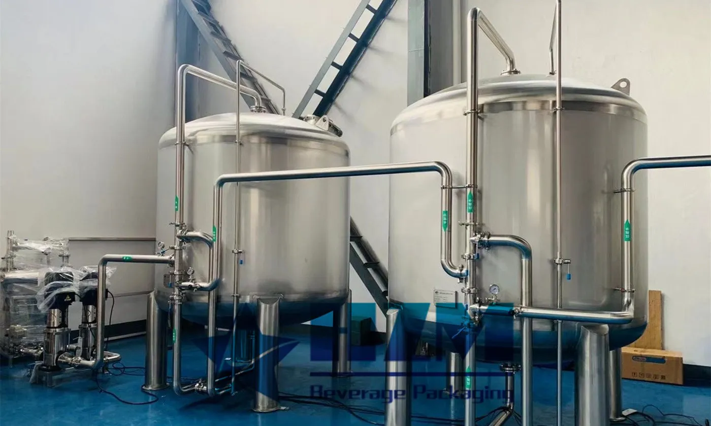
Equipment
RO System Water Treatment Plant
The RO water treatment plant produces purified water through feed-water pretreatment and reverse-osmosis membrane separation.
Learn moreEquipment
RO Water Treatment Machine for Bottled Water Production
10 T/H reverse osmosis water treatment for purified-water bottling, with pretreatment, storage and filler-supply connections.
Learn moreEquipment
Water Treatment for the Food & Beverage Industry – RO Water Treatment Equipment
10 T/H RO water treatment for ingredient, process and rinse water in food and beverage plants.
Learn moreEquipment
Industrial food water treatment equipment – 10T/H RO Water Treatment System
10 T/H reverse osmosis water treatment for food and beverage production, with pretreatment and stainless-steel equipment options.
Learn more2026-09-14
RO Membrane Scaling: How to Confirm It Before Cleaning
Do not identify scale from low flow alone. Use feed analysis, recovery, pH, concentrate chemistry, stage location and deposit analysis to distinguish carbonate, sulfate, silica or other scale before choosing a cleaner. Follow this practical fault-isolation, repair and prevention guide for bottling-line operators and maintenance teams.
Learn more2024-07-04
Commercial industrial reverse osmosis machine
Industrial reverse osmosis equipment is primarily used for producing pure water for industrial production. Depending on customer requirements, different process flows are employed to produce pure water that meets the specified standards. The equipment is widely used in the food and beverage industry, laboratories, pharmaceuticals, chemicals, and other sectors. Our equipment is factory-direct, and it is exported to more than 50 countries, including South Africa, North Africa, Sudan, the United States, Europe, and Southeast Asia.
Learn more2026-08-25
RO Permeate Conductivity Is High: Membrane, O-Ring or Process?
Confirm the conductivity instrument and temperature compensation, then determine whether the change affects one vessel, one stage or the whole train. Check recovery, oxidation, membrane damage, interconnector O-rings and permeate backpressure. Follow this practical fault-isolation, repair and prevention guide for bottling-line operators and maintenance teams.
Learn more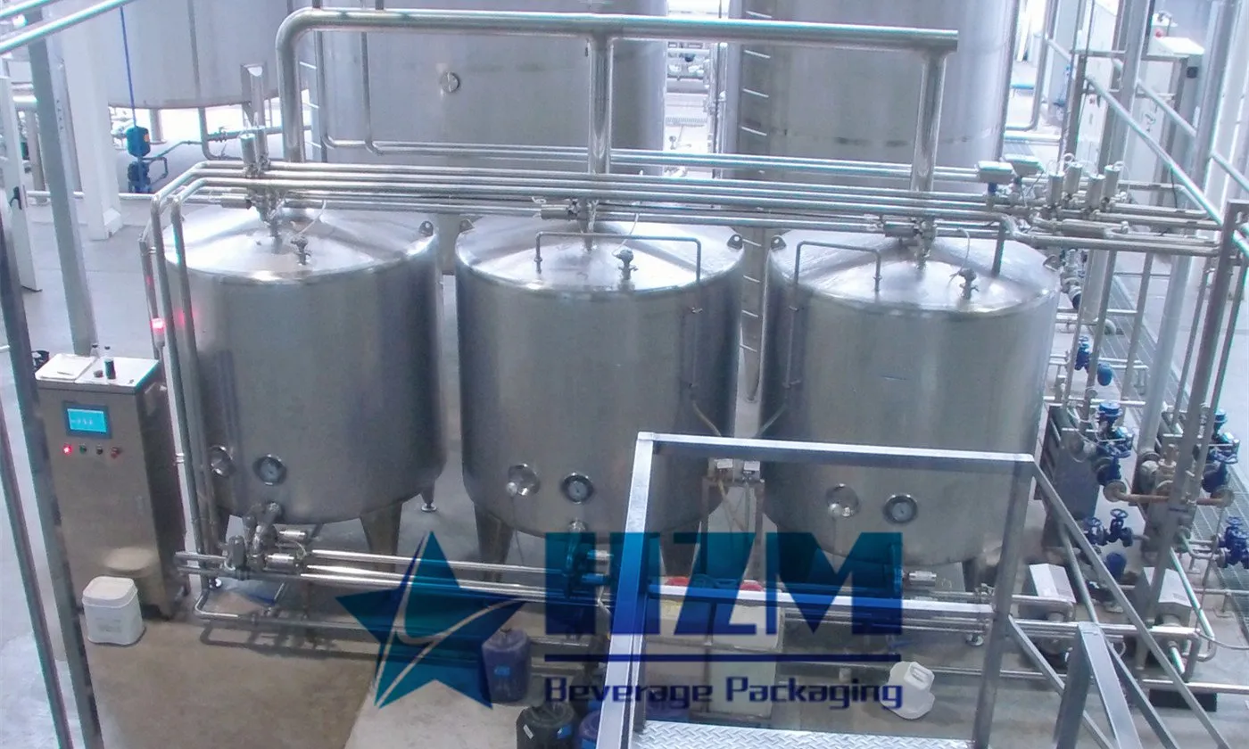
2024-05-14
What is a CIP cleaning system?
CIP cleaning system, also known as Clean In Place system, refers to a safe and automatic cleaning system that can be achieved through simple operation methods without dismantling production equipment.
Learn more2025-03-28
Principle and Application of CIP Cleaning System
The CIP cleaning system is an essential hygiene solution in water and beverage production. By providing an efficient and convenient cleaning process, it ensures equipment sanitation, improves production efficiency, extends equipment lifespan, and reduces energy consumption
Learn more2026-09-04
RO Differential Pressure Keeps Rising: Fouling Location Matters
Locate the stage where pressure loss is increasing and relate it to normalized flow and salt passage. A first-stage rise often points to particulate or biological fouling; a later-stage rise can indicate scale, but feed analysis is required. Follow this practical fault-isolation, repair and prevention guide for bottling-line operators and maintenance teams.
Learn more