
Insights & Updates
RO System Produces Too Little Permeate: A Data-Driven Diagnosis
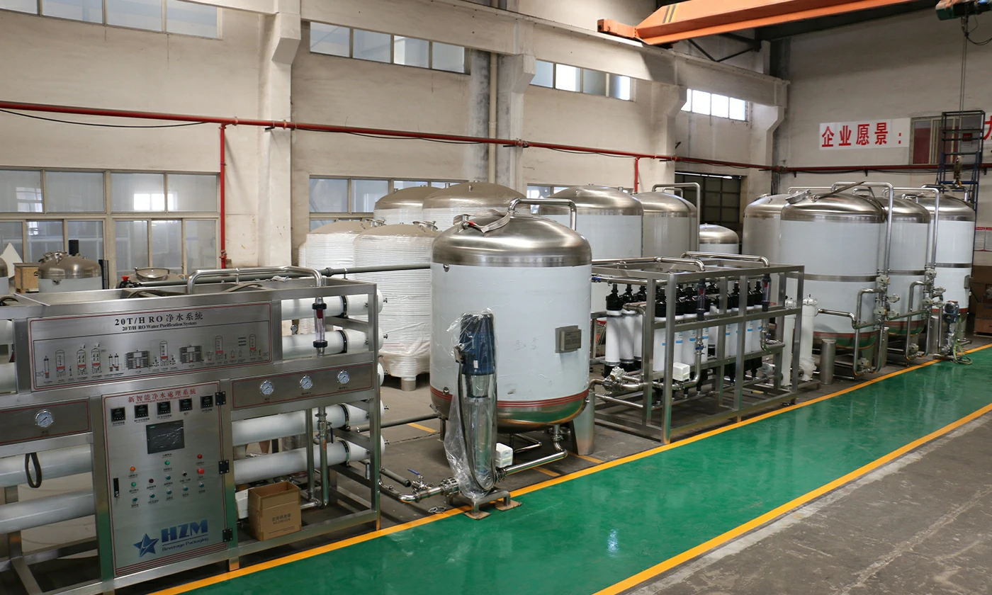
Low permeate flow from a reverse-osmosis system is easiest to solve while the original evidence is still available. Keep affected samples, record the operating state and resist making several adjustments at once.
Water-treatment performance must be evaluated with normalized operating data. Raw-water changes, temperature, recovery, pressure, flow and conductivity interact; a single gauge reading is not enough to identify membrane damage or fouling. For this fault, the first distinction is between lower feed-water temperature and insufficient net driving pressure. The procedure below moves from non-invasive checks to controlled repair and restart.
Quick answer: Normalize flow for temperature and pressure before declaring the membranes fouled. Then check feed availability, filter differential pressure, pump performance, recovery, concentrate restriction, scaling and biological or organic fouling.
What operators usually see
The failure pattern narrows the search more quickly than replacing parts. Mark samples and record which of these conditions are present: For this case, preserve evidence that shows whether permeate output falls while product-water conductivity remains normal.
- Permeate output falls while product-water conductivity remains normal
- Feed pressure rises to maintain the same output
- Flow is lowest during cold raw-water periods
- One RO stage shows a larger change than the others
Make the equipment safe and protect the product
Use the plant chemical-handling procedure, suitable PPE and lockout/tagout. Depressurize housings and verify that cleaning chemicals have been displaced before opening a pump, filter or membrane vessel.
Trend feed, concentrate and permeate flows; stage pressures; differential pressure; conductivity; temperature; pH; oxidant residual; and recovery. Compare normalized values with the accepted commissioning baseline. Explicitly record whether permeate output falls while product-water conductivity remains normal.
Most likely causes, in practical checking order
1. Lower feed-water temperature
Higher viscosity reduces membrane flux even when the membrane condition has not changed To test this explanation without guessing, record feed temperature, conductivity, pH, pressures and all three flows at stable operation Record the result before moving to the next cause.
2. Insufficient net driving pressure
Low pump discharge, high permeate backpressure or excess osmotic pressure reduces production A practical confirmation step is to calculate or use the approved normalization method to compare with the commissioning baseline. Compare the finding with a known-good run.
3. Scaling or fouling
Deposits add hydraulic resistance and may raise stage differential pressure Do not compensate for this condition in the recipe. First, check cartridge-filter and stage differential pressures Keep the original setting and measured result in the fault record.
4. Incorrect recovery or concentrate restriction
A valve position or flow-control change moves the system outside its design operating point Separate this cause from the others with one controlled check: verify pump speed, rotation, suction condition and discharge performance Use the same product, format and speed for the comparison.
Step-by-step diagnostic procedure
The aim is to eliminate whole groups of causes with each check. Record actual values rather than “normal” or “looks good.”
- Record feed temperature, conductivity, pH, pressures and all three flows at stable operation
- Calculate or use the approved normalization method to compare with the commissioning baseline
- Check cartridge-filter and stage differential pressures
- Verify pump speed, rotation, suction condition and discharge performance
- Calculate actual recovery and confirm concentrate flow path and valve position
- Review pretreatment, antiscalant, SDI or equivalent feed-quality data and cleaning history
Corrective actions that address the root cause
A reset is not a repair. Complete the mechanical, process or controls work indicated by the evidence and document the as-left state.
- Correct feed temperature expectation or operating target rather than overpressurizing cold membranes
- Restore pump, suction, valve and backpressure conditions
- Clean the membrane only with an approved procedure selected for the diagnosed foulant
- Return recovery and concentrate flow to the design window
How to verify the repair before full-speed production
Restart at reduced speed with normal production materials, then increase output in steps. The first acceptance check is: Confirm that low permeate flow from a reverse-osmosis system is absent for multiple consecutive cycles, not only for one sample. Review the alarm history and keep diagnostic product segregated until the site’s quality procedure releases it.
- Confirm that low permeate flow from a reverse-osmosis system is absent for multiple consecutive cycles, not only for one sample.
- Compare the repaired result for “Permeate output falls while product-water conductivity remains normal” with the approved quality limit and the last known-good baseline.
- Check adjacent stations and downstream package quality for side effects associated with lower feed-water temperature.
- For “RO System Produces Too Little Permeate: A Data-Driven Diagnosis”, record the final settings, measurements, parts used and restart authorization.
Prevent the problem from returning
The most effective preventive action is an observable limit with a named response, not a general instruction to “check regularly.”
- Trend normalized permeate flow rather than raw flow
- Alarm cartridge and stage differential pressure
- Record pretreatment quality and chemical dose
- Verify recovery every shift
- Trigger cleaning from normalized performance trends, not a calendar alone
When to stop troubleshooting and call a specialist
Stop and contact the machine or component supplier when low permeate flow from a reverse-osmosis system cannot be isolated with non-invasive checks, when it returns after an approved repair, or when calibration requires protected service tools. Escalate immediately for a damaged pressure boundary, uncontrolled motion, food-safety risk, exposed conductor or repeated protective trip. Send the service engineer the fault history, photos, samples, trend data, recipe revision and work already completed.
Relevant equipment for this application
The site example most closely related to low permeate flow from a reverse-osmosis system is the Industrial RO Drinking Water Treatment Plant – Reverse Osmosis Equipment for Beverage & Bottled Water. Equipment selection should be checked against samples, quality limits, required sustained output and available utilities.
Frequently asked questions
What should be checked first when low permeate flow from a reverse-osmosis system?
Normalize flow for temperature and pressure before declaring the membranes fouled. Then check feed availability, filter differential pressure, pump performance, recovery, concentrate restriction, scaling and biological or organic fouling. Preserve the original settings and take representative samples before repair work begins.
How can we distinguish lower feed-water temperature from insufficient net driving pressure?
Higher viscosity reduces membrane flux even when the membrane condition has not changed In contrast, low pump discharge, high permeate backpressure or excess osmotic pressure reduces production Compare the two mechanisms under the same operating condition by completing these checks: record feed temperature, conductivity, pH, pressures and all three flows at stable operation Then calculate or use the approved normalization method to compare with the commissioning baseline
Can production continue while low permeate flow from a reverse-osmosis system?
Only when the plant’s documented risk assessment and quality procedure allow it. For low permeate flow from a reverse-osmosis system, stop and segregate production when package integrity, sanitation, validated processing, pressure safety, electrical protection or an uncontrolled reject trend is involved.
What evidence will help the equipment supplier respond faster?
Provide the model and serial number, product and format, target speed, first fault, timestamps, photos or video, affected station pattern and maintenance history. For this issue, also include permeate output falls while product-water conductivity remains normal and the measured result from this check: review pretreatment, antiscalant, SDI or equivalent feed-quality data and cleaning history
Talk to our engineering team
Need help planning your packaging line?
Share your product, bottle and capacity requirements for a practical equipment recommendation.
Equipment
Industrial RO Drinking Water Treatment Plant – Reverse Osmosis Equipment for Beverage & Bottled Water
1,000 litres/hour reverse osmosis water treatment for bottled-water, beverage and food production.
Learn more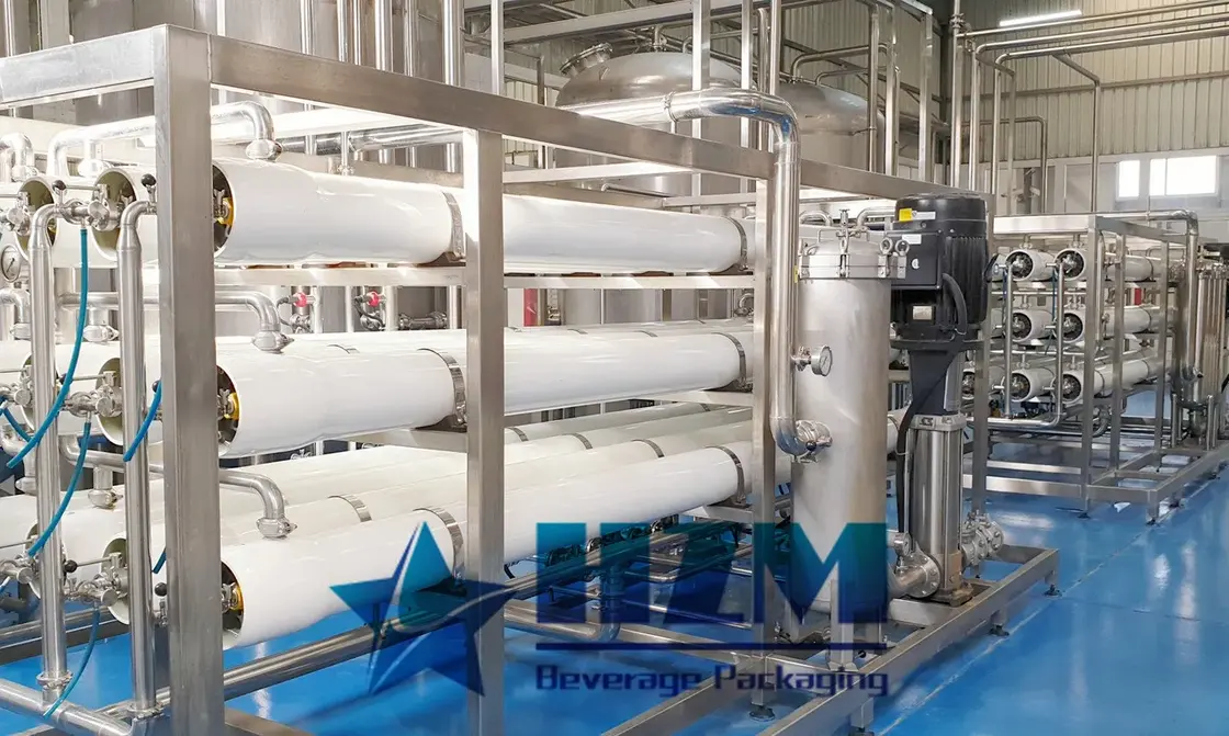
Equipment
Water Treatment System
HZM water treatment systems prepare process water for bottled water, beverages and brewing.
Learn more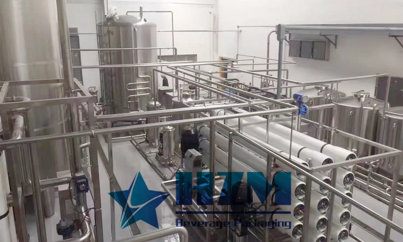
Equipment
Water Treatment Machine Purification System
HZM water purification equipment combines filtration, membrane treatment and final treatment in one process.
Learn more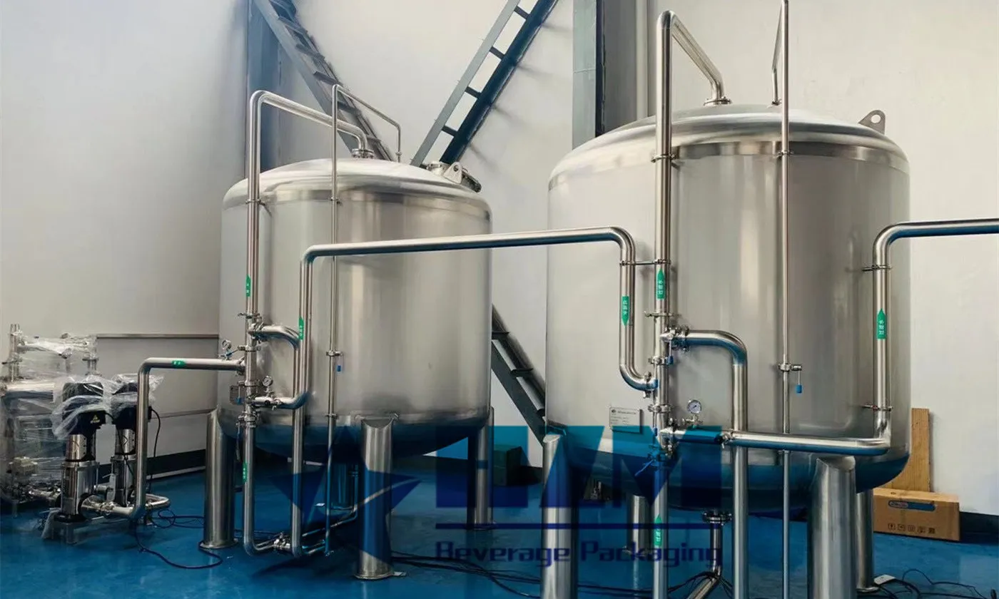
Equipment
RO System Water Treatment Plant
The RO water treatment plant produces purified water through feed-water pretreatment and reverse-osmosis membrane separation.
Learn more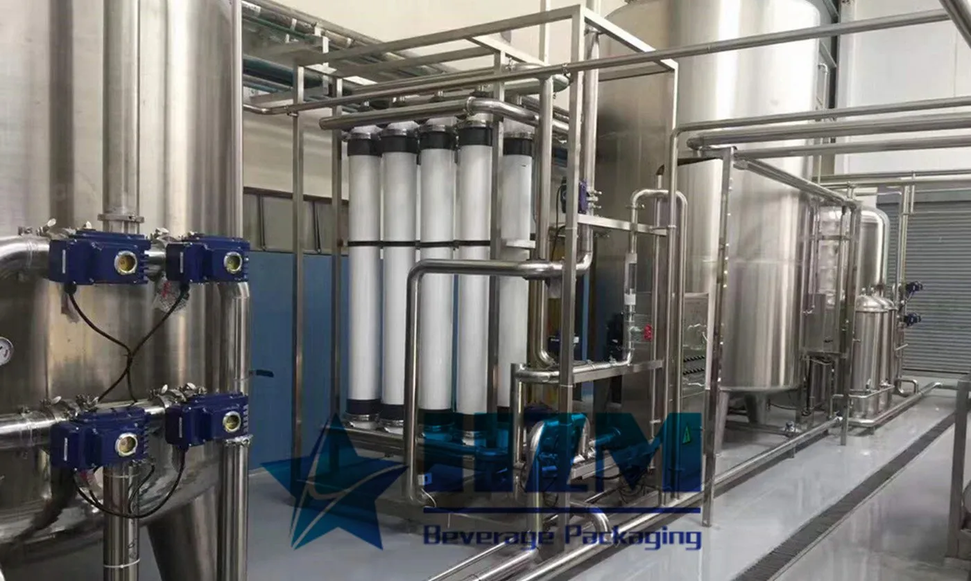
Equipment
Industrial Drinking Water Treatment System
This industrial drinking-water treatment system supplies treated water to bottling and beverage plants.
Learn more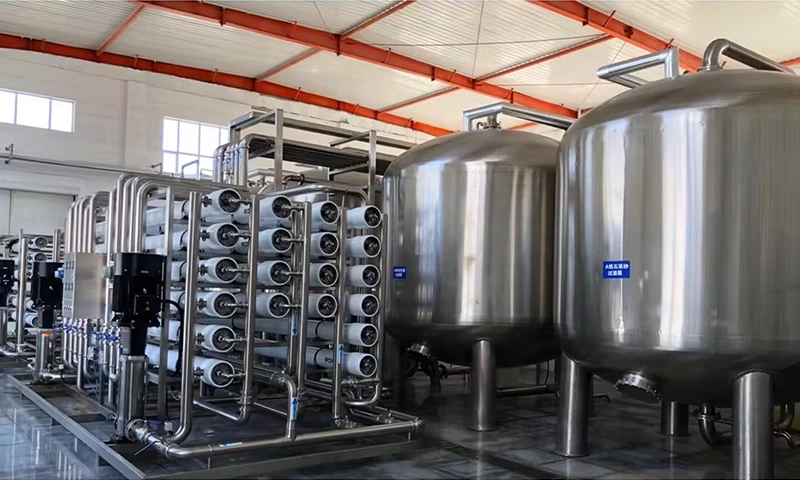
Equipment
reverse osmosis water treatment
The reverse osmosis system treats water for bottled-water and beverage production.
Learn moreEquipment
Industrial food water treatment equipment – 10T/H RO Water Treatment System
10 T/H reverse osmosis water treatment for food and beverage production, with pretreatment and stainless-steel equipment options.
Learn moreEquipment
RO Water Treatment Machine for Bottled Water Production
10 T/H reverse osmosis water treatment for purified-water bottling, with pretreatment, storage and filler-supply connections.
Learn moreEquipment
Water Treatment for the Food & Beverage Industry – RO Water Treatment Equipment
10 T/H RO water treatment for ingredient, process and rinse water in food and beverage plants.
Learn more2026-08-25
RO Permeate Conductivity Is High: Membrane, O-Ring or Process?
Confirm the conductivity instrument and temperature compensation, then determine whether the change affects one vessel, one stage or the whole train. Check recovery, oxidation, membrane damage, interconnector O-rings and permeate backpressure. Follow this practical fault-isolation, repair and prevention guide for bottling-line operators and maintenance teams.
Learn more2024-07-04
Commercial industrial reverse osmosis machine
Industrial reverse osmosis equipment is primarily used for producing pure water for industrial production. Depending on customer requirements, different process flows are employed to produce pure water that meets the specified standards. The equipment is widely used in the food and beverage industry, laboratories, pharmaceuticals, chemicals, and other sectors. Our equipment is factory-direct, and it is exported to more than 50 countries, including South Africa, North Africa, Sudan, the United States, Europe, and Southeast Asia.
Learn more2026-09-14
RO Membrane Scaling: How to Confirm It Before Cleaning
Do not identify scale from low flow alone. Use feed analysis, recovery, pH, concentrate chemistry, stage location and deposit analysis to distinguish carbonate, sulfate, silica or other scale before choosing a cleaner. Follow this practical fault-isolation, repair and prevention guide for bottling-line operators and maintenance teams.
Learn more2026-09-04
RO Differential Pressure Keeps Rising: Fouling Location Matters
Locate the stage where pressure loss is increasing and relate it to normalized flow and salt passage. A first-stage rise often points to particulate or biological fouling; a later-stage rise can indicate scale, but feed analysis is required. Follow this practical fault-isolation, repair and prevention guide for bottling-line operators and maintenance teams.
Learn more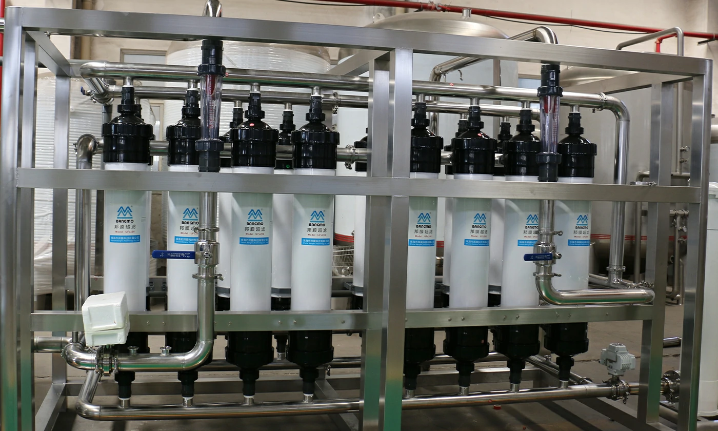
2026-01-22
Raw Water Treatment System for Beverage Plant
A reliable raw water treatment system is the foundation of any beverage production line. Whether producing bottled water, carbonated drinks, juice, or functional beverages, the quality of raw water directly affects product taste, safety, equipment lifespan, and regulatory compliance.
Learn more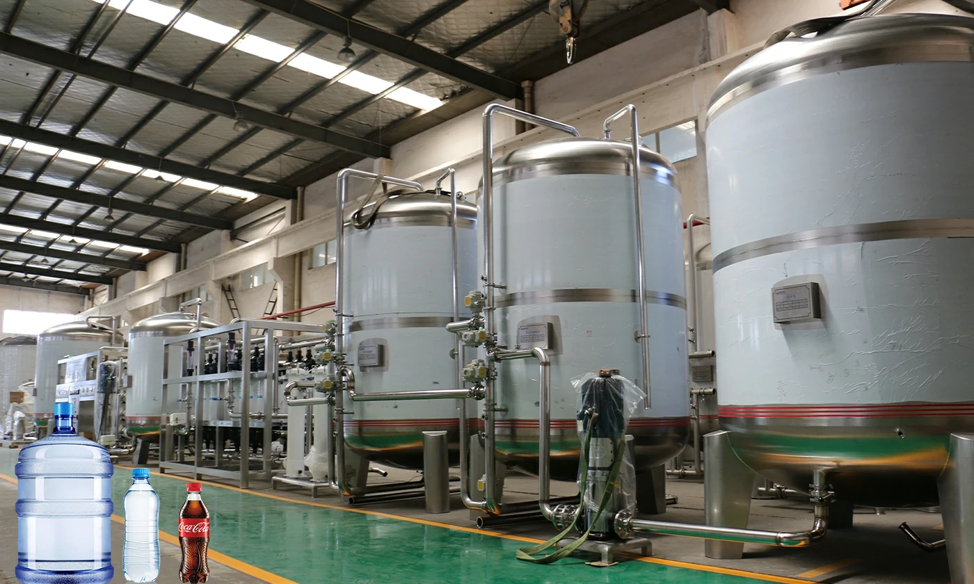
2026-07-25
Raw Water Analysis for a Bottling Plant: What to Test Before Buying RO Equipment
Learn which raw-water test results an equipment supplier needs to design pretreatment and RO capacity for a reliable bottled-water or beverage plant.
Learn more