
Insights & Updates
CIP Cleaning for Juice Filling Machines: Process and System Selection
Cleaning-in-place is a controlled process for cleaning the internal product-contact surfaces of beverage tanks, pipelines and filling equipment without dismantling the complete system. In a juice plant, a well-designed CIP program supports product quality, predictable changeovers and safer operation. It is not simply a “self-cleaning” feature and it should not be selected from tank volume alone.
HZM configures a CIP system from the connected equipment, circuit volume, cleaning recipe, required flow and temperature. The final recipe must also follow the beverage formulation, soil type, equipment supplier instructions and the plant’s food-safety plan.
What a CIP system needs to clean
Begin by listing every item that will be included in a cleaning circuit: mixing tanks, balance tanks, heat exchangers, product pipelines, valves, pumps, filler bowl, filling valves and return lines. Surfaces that cannot receive the required cleaning action need a separate method or a design change.
Long pipelines, parallel branches and equipment with different pressure limits should not be grouped automatically. The circuit design must provide suitable flow through the complete path while respecting the operating limits of every component. In larger plants, separate circuits may allow one area to be cleaned while another is prepared for production.
The four variables that control cleaning
- Mechanical action: sufficient, verified circulation through pipes and equipment helps remove residues.
- Time: each stage needs an established contact and circulation period.
- Temperature: heating can improve cleaning performance, but the setpoint must suit the detergent, soil and equipment materials.
- Chemical concentration: the selected detergent and concentration must follow the validated cleaning program and chemical supplier guidance.
Changing one variable affects the others. A generic temperature or concentration copied from another factory is not a safe substitute for validation. Juice containing pulp, protein or stabilizers may leave different residues from a clear beverage and can require a different sequence.
A typical cycle structure
A plant-specific cycle may include product recovery or drain-down, a pre-rinse, detergent circulation, an intermediate rinse, a second detergent or sanitation stage when required, and a final rinse. The sequence, reuse policy and release criteria should be documented. Operators should be able to see which circuit is active and whether the required conditions have been reached.
For a complete juice project, CIP must be coordinated with the beverage processing system, product transfer and the selected juice filling equipment. Hygienic piping, drainability and valve selection are as important as the CIP tanks themselves.
Manual, semi-automatic or automatic control
A manual system may be suitable for a small, simple circuit when the plant can manage each action under a documented procedure. Semi-automatic control can maintain selected variables while operators perform routing steps. A fully automatic system can control recipes, valve sequences, circulation, alarms and records, subject to the confirmed instrumentation and scope.
Automation does not remove the need for verification. Sensors must be located correctly, calibrated and maintained. Interlocks should prevent an unsafe route, incompatible valve position or transfer of cleaning liquid into product. Access permissions and recipe change control help protect validated settings.
Recovery, utilities and operating cost
The number and size of CIP tanks affect water use, chemical recovery, heating duty, floor space and cycle time. A recovery arrangement can reduce waste when the returned solution remains within the plant’s reuse criteria. The proposal should state the heating method, tank arrangement, circuit count, pump duty, instrumentation and the battery limits for utilities.
Ask for estimated water, heating and chemical demand based on the proposed recipe rather than relying on a general claim of cost savings. The factory must also plan safe chemical storage, dosing, ventilation, drainage and personal protection according to local rules and chemical safety information.
How to verify cleaning performance
Cycle records can show that target time, temperature, flow or conductivity conditions were achieved, but those records alone do not prove that every surface is clean. A validation plan may include visual inspection where possible, rinse-water checks, hygiene testing and periodic inspection of difficult locations. The exact release criteria belong in the plant’s quality system.
Information to send with a CIP inquiry
- Product recipes and the main residues expected after production.
- A process flow diagram and list of tanks, pipes and machines.
- Pipe sizes, approximate lengths, elevations and circuit volumes.
- Required number of independent or simultaneous circuits.
- Equipment pressure and temperature limits.
- Available steam or hot water, electricity, water and drainage.
- Cleaning chemicals already approved by the factory.
- Required automation, reports and connection to the line control system.
Frequently asked questions
Can a CIP system clean every part of a filler?
Only the surfaces included in a designed circulation path can be cleaned in place. External surfaces, cap-handling components and non-circulated areas need their own cleaning procedures. Confirm the filler supplier’s CIP boundary before finalizing the system.
Is stainless steel alone enough for hygienic operation?
No. Material grade is only one factor. Surface condition, weld quality, seals, valve design, drainability, dead legs, cleaning access and operating procedures all influence hygiene.
When should the CIP design be finalized?
It should be developed together with the process and filling line, before piping and layout are frozen. This allows return routes, utility loads and cleaning circuits to be engineered into the project instead of added later.
Talk to our engineering team
Need help planning your packaging line?
Share your product, bottle and capacity requirements for a practical equipment recommendation.
Equipment
CIP System
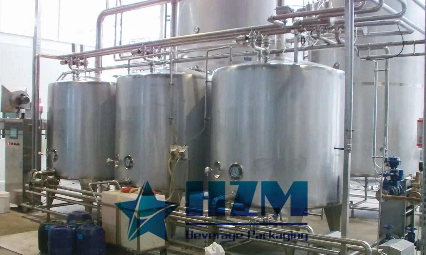
The CIP system cleans the internal surfaces of beverage tanks, pipelines and filling equipment without routine disassembly.
Learn more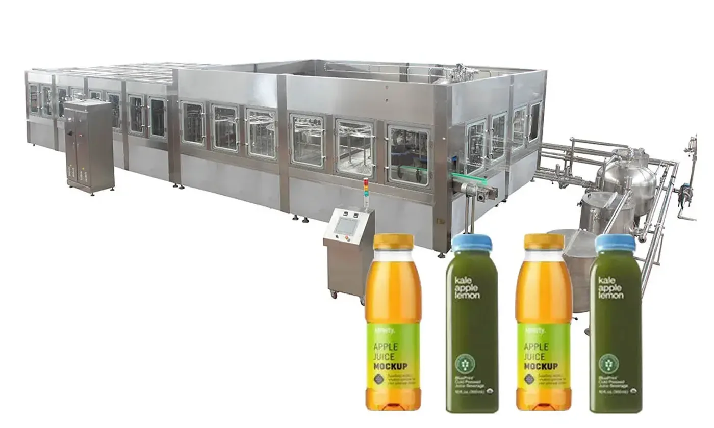
Equipment
Bottled Juice Packaging Machine
Bottled juice filling equipment with rinsing and capping, from 6,000 to 18,000 bottles/hour at 500 ml.
Learn more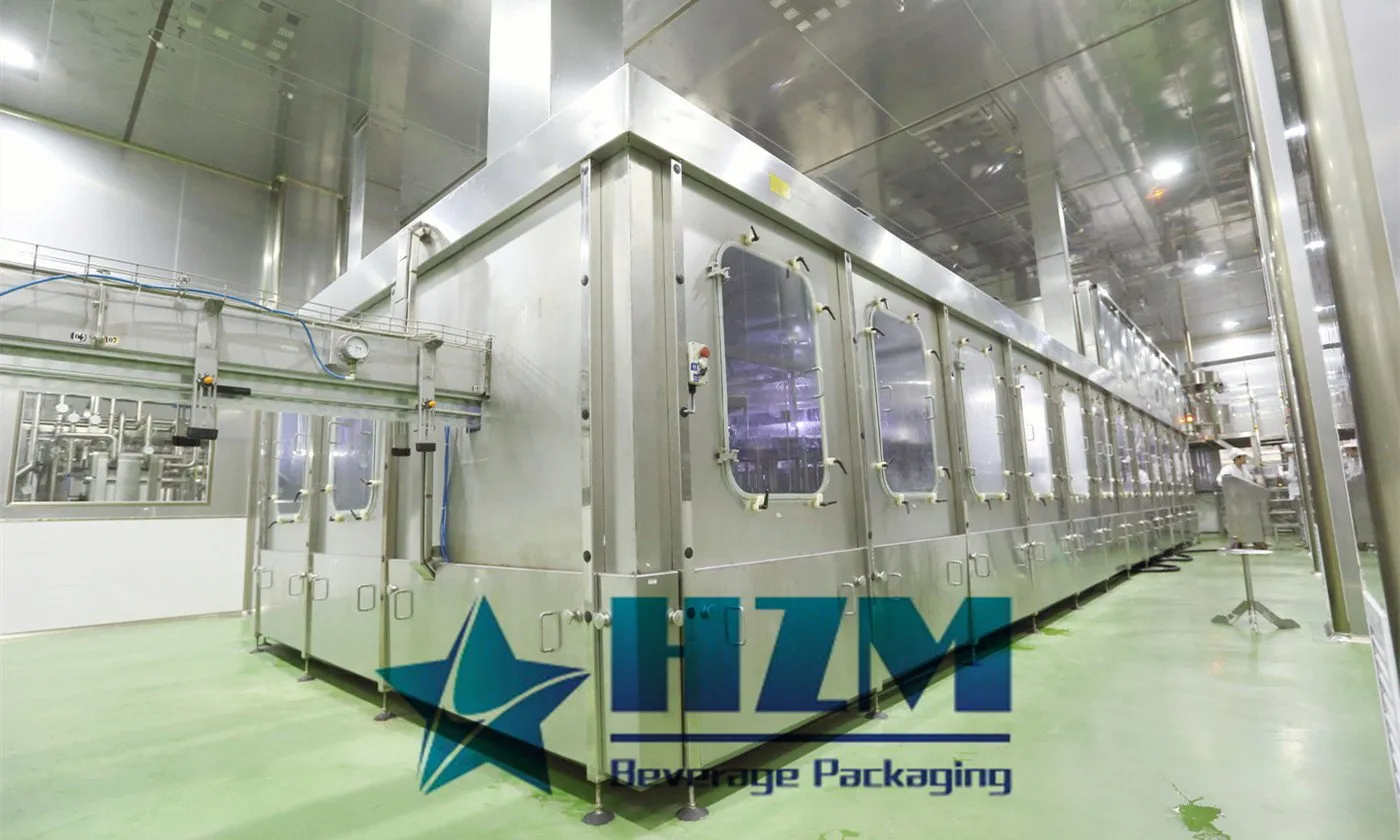
Equipment
PET Bottle Juice Beverage Filling Machine
PET bottle juice filling with automatic rinsing and capping, for juice, tea and still beverages.
Learn more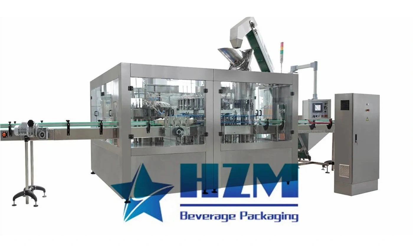
Equipment
Glass Bottle Juice Beverage Filling Machine
Glass bottle juice filling with rinsing and capping, for juice, tea and other still beverages.
Learn more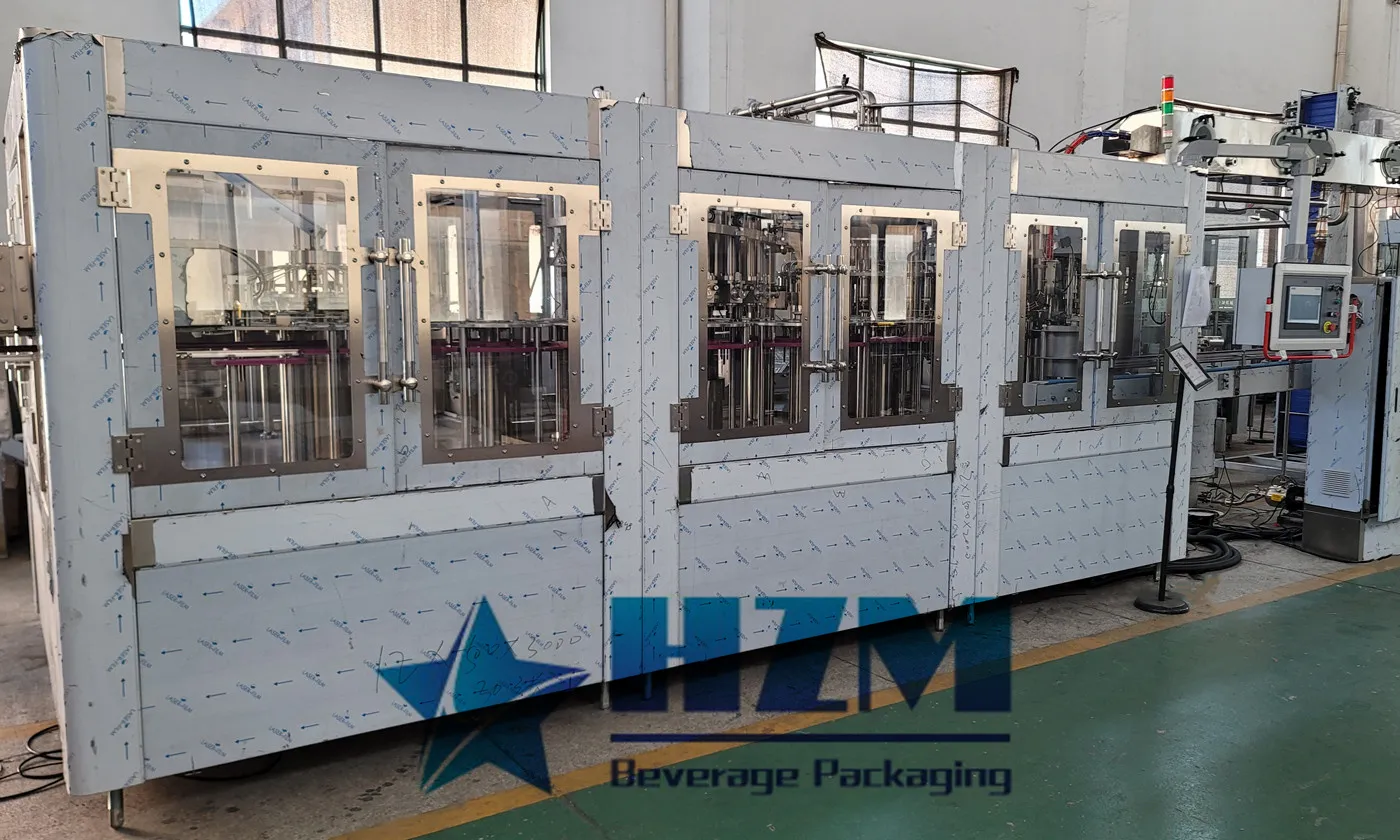
Equipment
Automatic Pulp Juice Filling Machine
Pulp juice filling with separate pulp and liquid dosing, bottle rinsing and capping for beverages containing fruit particles.
Learn more
Equipment
PET Bottle juice Beverage Hot Filling Machine
Hot filling for juice and tea in heat-compatible PET bottles, with automatic rinsing, filling and capping.
Learn more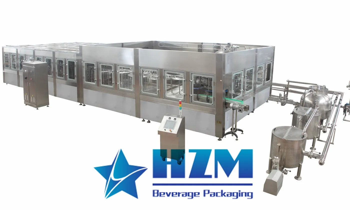
Equipment
Moderate Temperature Juice Filling Machine
Moderate-temperature juice filling with automatic bottle rinsing and capping, with XXGF models from 6,000 to 24,000 bottles/hour at 500 ml.
Learn more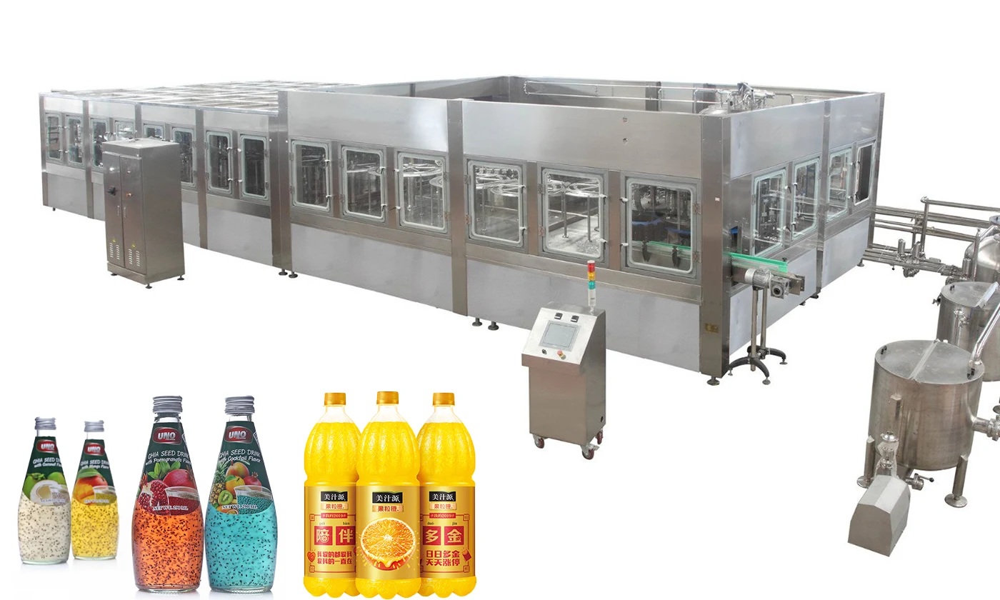
Equipment
juice Pulp Filling Machine 4 in 1
RXGGF16-16-5 pulp juice filling with separate pulp and liquid dosing, rinsing and capping at 5,000 bottles/hour for 250 ml bottles.
Learn more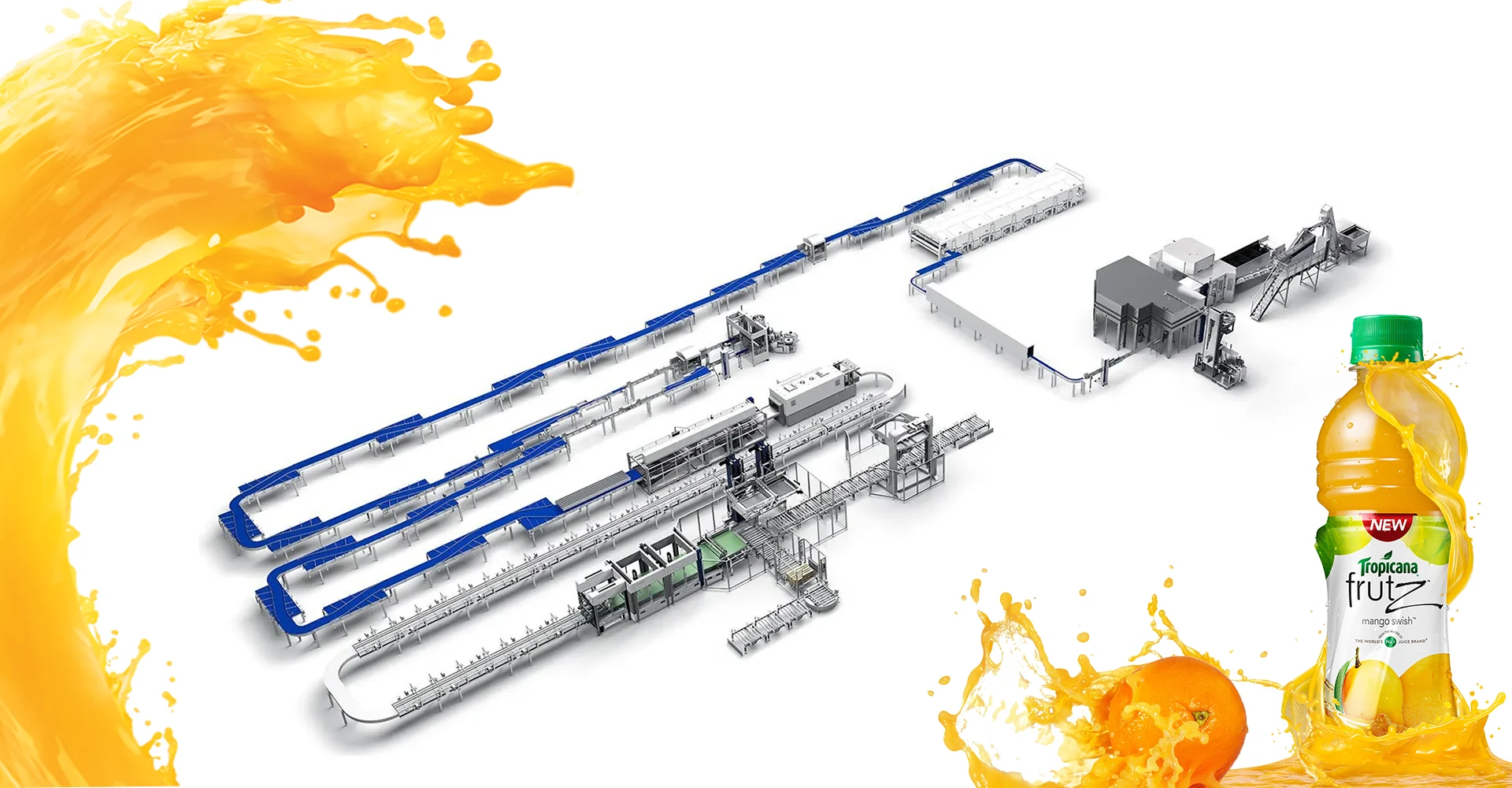
Equipment
Juice beverage bottling line
The juice beverage bottling line connects beverage preparation and thermal processing with bottle filling, capping, labelling and packing.
Learn more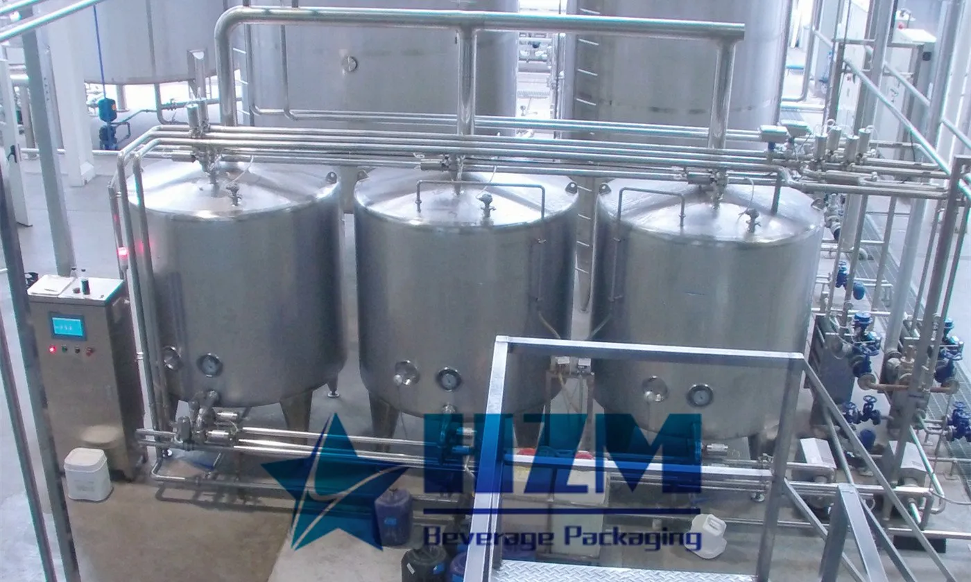
2024-05-14
What is a CIP cleaning system?
CIP cleaning system, also known as Clean In Place system, refers to a safe and automatic cleaning system that can be achieved through simple operation methods without dismantling production equipment.
Learn more2025-03-28
Principle and Application of CIP Cleaning System
The CIP cleaning system is an essential hygiene solution in water and beverage production. By providing an efficient and convenient cleaning process, it ensures equipment sanitation, improves production efficiency, extends equipment lifespan, and reduces energy consumption
Learn more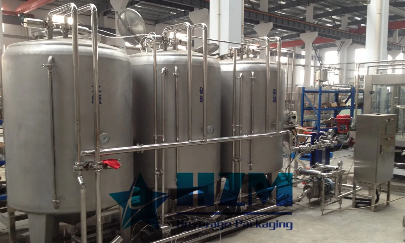
2025-03-02
The Role of the CIP Cleaning System in Water and Beverage Production Lines
The CIP system effectively removes these residues from the inner walls of pipelines, tanks, valves, and other equipment through powerful cleaning and sterilization, preventing microbial contamination and ensuring that products meet hygiene standards.
Learn more
2023-12-04
Why Beverage Filling Machines Must Have CIP Cleaning Systems?
CIP (Cleaning In Place) cleaning systems are essential in the realm of food and beverage production, particularly for dairy processing equipment and pipelines. Over time, these components accumulate deposits that, if not cleaned thoroughly and promptly, can directly impact product quality and result in various issues such as substandard packaged foods.
Learn more2023-06-09
Juice and Tea Filling Line Guide: CIP Coverage and Cleaning Validation
Practical HZM guidance on juice and tea filling line, focused on cip coverage and cleaning validation, line integration, RFQ data and measurable acceptance checks.
Learn more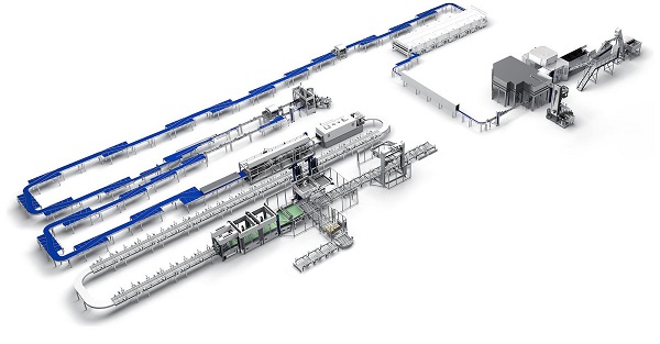
2026-10-16
Juice Line Loses Too Much Product During CIP and Changeover
Measure product, water and waste around every transition. Identify mixing zones, tank heel, pipe hold-up, valve leakage, interface detection and late operator decisions before changing the validated sanitation process. Follow this practical fault-isolation, repair and prevention guide for bottling-line operators and maintenance teams.
Learn more