
Insights & Updates
Key Components of a Filling Machine: Rinsing, Filling and Capping Explained
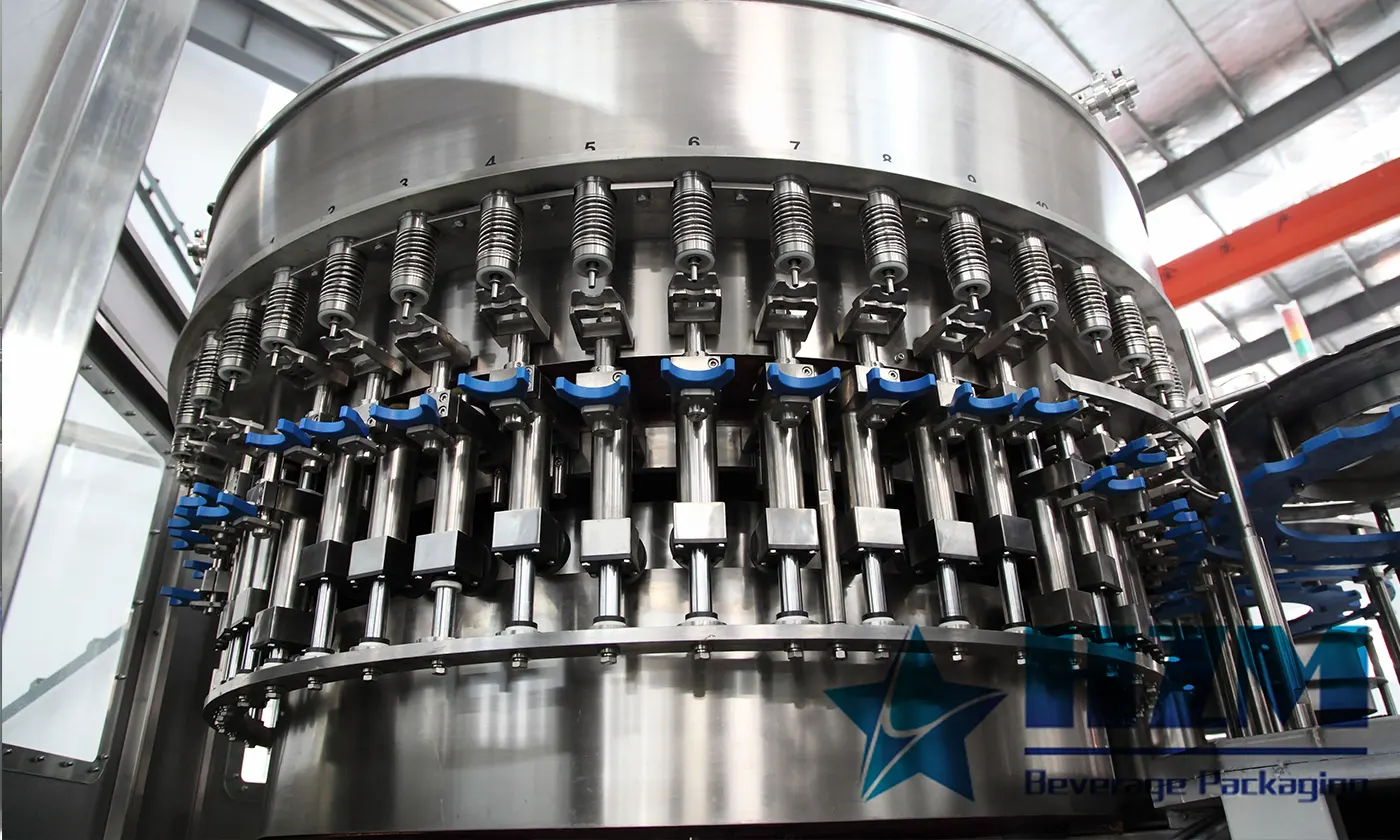
A beverage filling machine is a coordinated system, not a single valve that dispenses liquid. Container transfers, the product circuit, filling valves, cap handling, drives, sensors and controls must remain synchronized. When one component is poorly matched, the visible symptom may appear somewhere else—for example, an unstable infeed can look like a filler-capacity problem.
Bottle handling, filling valves, capping heads and controls each affect output, hygiene and maintenance access on a rotary bottling line.
1. Machine frame, enclosure and base
The frame supports rotating assemblies and keeps them aligned under continuous load. Product-contact areas need suitable corrosion resistance and cleanable surfaces, while guarding prevents access to moving parts during operation. The base should manage rinse water and product drainage without allowing standing liquid around bearings or electrical components.
Inspect access as well as appearance. Operators need to see transfers and maintenance personnel need safe access to lubrication, adjustment and replacement points.
2. Container infeed and transfer system
Containers normally enter through conveyors, spacing devices and star wheels before moving into the rinser or filler. PET bottles may be handled by the neck, while glass bottles and cans require geometry suited to their body and base.
Guides, screws and star wheels must match the container drawing. Worn or incorrect change parts can cause scuffing, tipping and intermittent jams. The infeed must also respond predictably when upstream or downstream equipment changes speed.
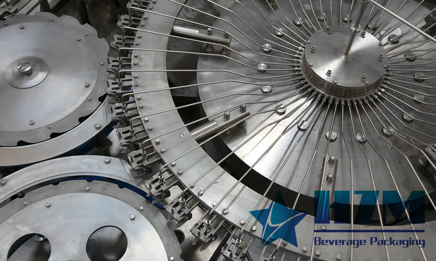
3. Bottle rinsing mechanism
The rinser grips or supports empty containers, inverts them where applicable, applies the specified rinsing medium and allows enough drainage before transfer. The process may use treated water, sterile water or another validated method depending on the product and hygiene plan.
Important design points include nozzle alignment, rinse coverage, drain management, gripper suitability and protection against cross-contamination. “No bottle, no rinse” control reduces unnecessary utility use.
4. Product tank and supply circuit
The filler bowl or product tank provides a stable supply to the valves. Its level, pressure and temperature can directly affect filling consistency. The upstream pump, balance tank, filters and heat exchanger should therefore be sized for the full operating range, not only the nominal average flow.
The circuit should support hygienic cleaning and drainage. Instrumentation may include level, pressure and temperature measurement depending on the application. Carbonated products additionally require stable product carbonation and controlled pressure.
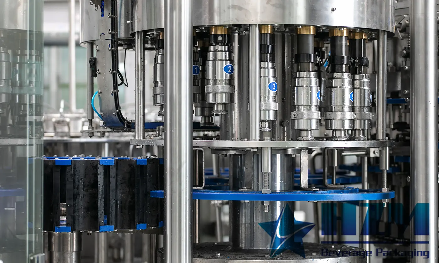
5. Filling valves and lifting or support assemblies
The valve is selected around beverage properties and the required filling method. Still water may use normal-pressure or gravity filling; carbonated beverages commonly use isobaric filling; viscous products may use flowmeter, piston or weight-based approaches.
Each container must arrive in the correct position and form a reliable relationship with the valve. Valve opening, venting and closing need repeatable timing. Dripping, foaming or position-specific fill variation can indicate worn seals, a restricted vent, unstable supply conditions or incorrect setup.
6. Cap elevator, sorter and chute
Caps are elevated, oriented and delivered through a chute to the pickup or placement point. Cap dust, deformation, static and inconsistent dimensions can interrupt feeding even when the capper itself is functioning correctly.
Look for accessible cleaning, low-cap detection and a way to reject incorrectly oriented caps. Product and packaging specifications should define allowable cap variation; forcing a poor cap through mechanical adjustment creates unstable operation.
7. Capping or seaming system
Plastic screw caps may use torque-controlled heads, while crown caps, aluminum closures and can ends require different mechanisms. The component must create a secure seal without damaging the neck finish or closure.
Measure the result using a suitable quality method. For screw caps this may include application and removal torque plus leak testing. For cans, seam dimensions and teardown checks are essential. Appearance alone cannot confirm seal integrity.
8. Main drive and transmission
Motors, gearboxes, shafts and timing elements keep the rinser, filler, capper and transfer stars synchronized. Sudden noise, heat or vibration needs investigation before it becomes a major alignment or bearing failure.
Change speed through the approved control method. Mechanical timing should not be adjusted to hide container or setup problems without identifying the root cause.
9. Sensors and inspection devices
Photoelectric sensors detect container flow and can enable functions such as “no bottle, no fill” and “no bottle, no cap.” Other devices may monitor tank level, pressure, guard position and cap supply. Downstream inspection can check fill level, cap presence, label placement or code quality.
Sensor location matters. Foam, condensation, reflected light and transparent bottles can affect detection. Use the correct sensor type and mounting, then document the stable setting rather than repeatedly increasing sensitivity.
10. Electrical controls, HMI and recipes
The programmable control system coordinates motion, interlocks, alarms and communication with adjacent equipment. The HMI should show clear machine states and actionable fault information. Recipe control helps repeat changeovers, but mechanical change parts and verification checks remain necessary.
Back up authorized programs and record parameter changes. Access levels should prevent accidental modification of critical settings while allowing trained operators to complete normal production tasks.
How the components affect one another
A stable filler depends on stable incoming containers, product and caps. For example, changing a bottle can affect infeed guides, rinser grips, valve sealing, star wheels, capper height and downstream labels. A component-by-component quotation will miss these interfaces.
When selecting filling equipment, supply actual beverage specifications, bottle and closure drawings, samples, required output and cleaning expectations. For compact PET applications, review a rinsing, filling and capping monoblock as part of the complete upstream and downstream line.
Practical acceptance checks
- Run representative containers and closures, including the most difficult format.
- Measure output as saleable, correctly filled and correctly closed packages.
- Check every filling and capping position, not only average results.
- Demonstrate normal stops, restart, low-product and low-cap conditions.
- Complete a planned changeover and record the required parts and time.
- Verify cleaning steps, safety devices, documents and recommended spares.
Understanding the components makes troubleshooting and purchasing more objective. Instead of asking only “How fast is the machine?”, ask how the complete system will handle the actual beverage, container, closure and daily operating plan.
Talk to our engineering team
Need help planning your packaging line?
Share your product, bottle and capacity requirements for a practical equipment recommendation.
Equipment
Rinsing, Filling And Capping Monoblock Machines
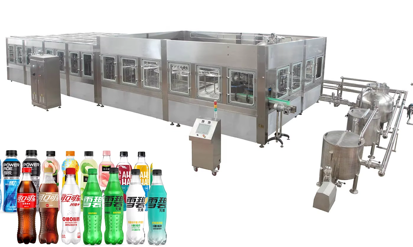
HZM monoblock machines combine bottle rinsing, filling and capping in a continuous operation.
Learn more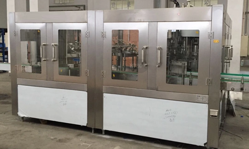
Equipment
10L Water Filling Machine 1200BPH – Automatic Washing Filling Capping Machine
RSXGF12-12-5(110Π) automatic rinsing, filling and capping for 10 L water bottles at 1,100–1,200 bottles/hour.
Learn more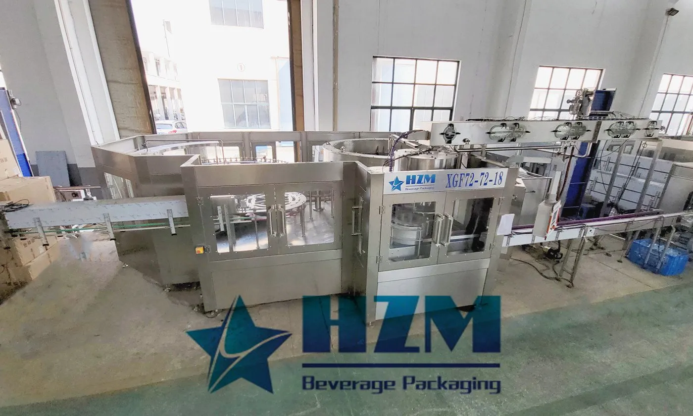
Equipment
Automatic Water Bottle Filling Machine
Automatic rinsing, filling and capping for purified and mineral water in PET bottles, with capacities of 5,000–42,000 bottles/hour at 500 ml.
Learn more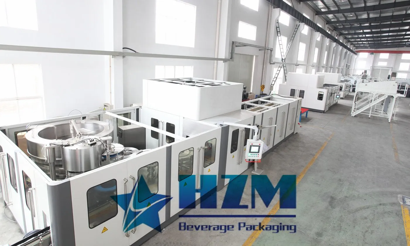
Equipment
Blowing-Filling-Capping Machine
A PET combiblock that combines preform heating, bottle blowing, filling and capping at 12,000–48,000 bottles/hour at 500 ml.
Learn more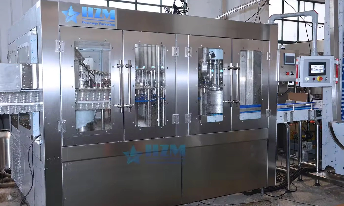
Equipment
Bottle Washing-Filling-Capping Machine
Large-bottle water rinsing, filling and capping with design outputs of 1,500 bottles/hour at 5 L, 1,000 at 7 L and 700 at 10 L.
Learn more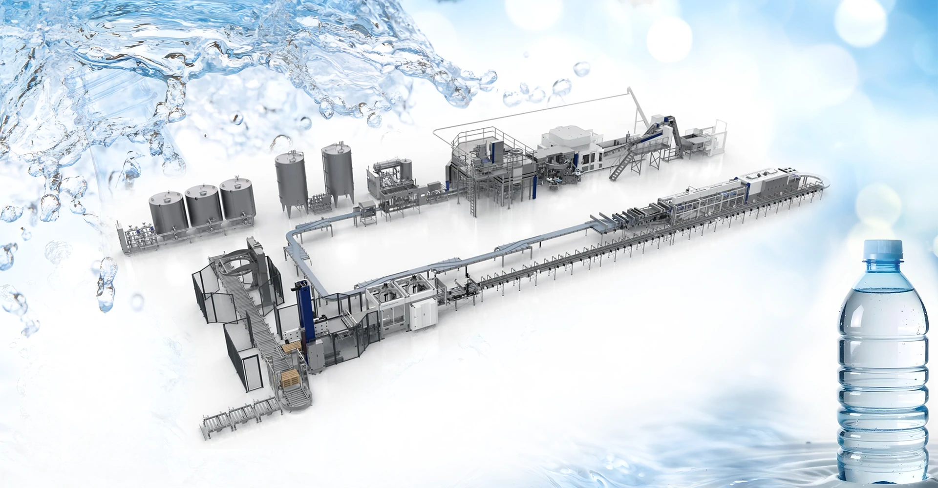
Equipment
Drinking water production line – Bottled Water Filling Machine Manufacturer
PET-bottled drinking-water production with automatic rinsing, filling and capping, plus water treatment and packaging equipment.
Learn more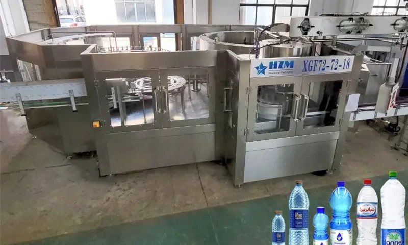
Equipment
3-In-1 Water Bottle Filling Machine
A 3-in-1 PET bottle rinsing, filling and capping machine for drinking water, from 5,000 to 18,000 bottles/hour at 500 ml.
Learn more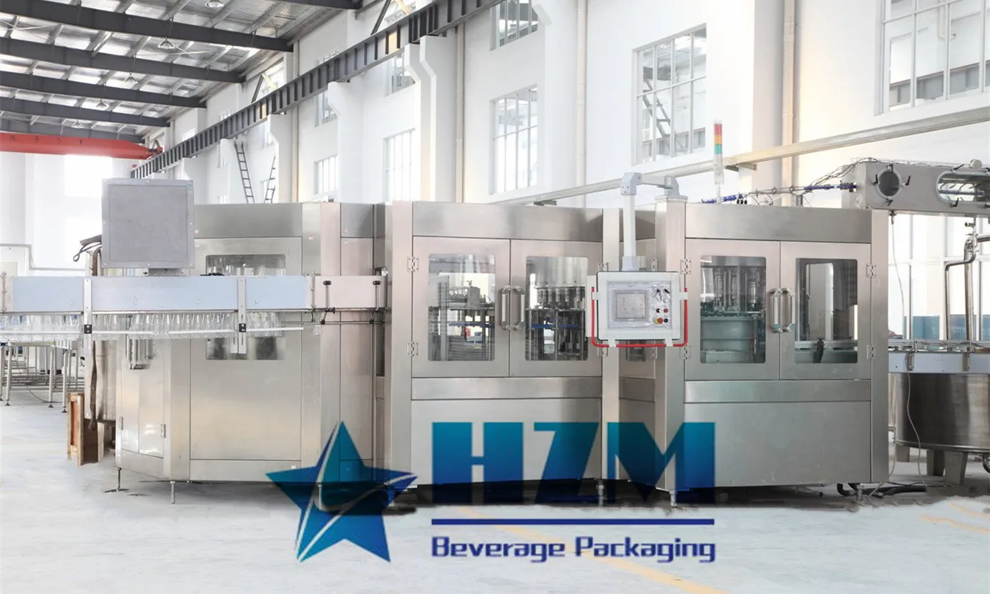
Equipment
PET Bottle Water Filling Machine
PET bottle water filling with automatic rinsing and capping, for purified water, mineral water and still drinking water.
Learn more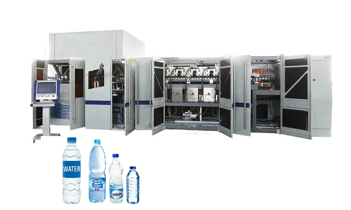
Equipment
Automatic PET Bottle Blowing Filling Capping Machine – Best price beverage machinery
Automatic PET bottle blowing, filling and capping, with capacities of 12,000–48,000 bottles/hour at 500 ml and bottle volumes up to 2 L.
Learn more2023-06-09
SS316 Pressure Type HMI Rinsing Filling Capping Machine
High quality SS316 Pressure Type HMI Rinsing Filling Capping Machine from China, China's leading HMI Rinsing Filling Capping Machine product, with strict quality control SS316 Rinsing Filling Capping Machine factories, producing high quality CE Rinsing Filling Capping Machine products.
Learn more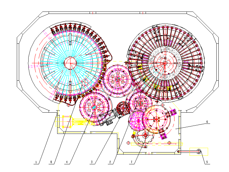
2025-02-05
How a 3-in-1 Isobaric Filling Machine Works: Rinsing, Filling and Capping
Understand the operating sequence of a 3-in-1 isobaric filling machine for carbonated beverages, the critical pressure and temperature controls, and common causes of foam, underfill and cap defects.
Learn more2026-03-20
CE Certified 5L 6000BPH PET Bottle Filling And Capping Machine
Discover the CE certified 5L 6000BPH PET bottle filling and capping machine. High efficiency, automatic operation, ideal for 3L–10L bottled water production lines.
Learn more2023-06-09
Three Rinsing Filling Capping 5 in 1 Monoblock Machine
High quality Three Rinsing Filling Capping 5 in 1 Monoblock Machine from China, China's leading spout pouch filling and capping machine product, with strict quality control Spout Pouch Filling Capping Machine factories, producing high quality 1500bph Pouch Filling And Capping Machine products.
Learn more2023-06-09
60 Bottle Rinsing Clip 36000 BPH Auto Water Filling Machine
High quality 60 Bottle Rinsing Clip 36000 BPH Auto Water Filling Machine from China, China's leading 36000 Bpm Auto Water Filling Machine product, with strict quality control 1500ml auto water filling machine factories, producing high quality 1500ml washing filling and capping machine products.
Learn more2023-11-11
3-in-1 Beverage Filling Machine: Combining Bottle Washing, Filling, and Capping
A 3-in-1 beverage filling machine is an efficient automated device that integrates three crucial steps in the beverage production process: bottle washing, filling, and capping. Here is a detailed introduction to the three-in-one beverage filling machine.
Learn more